DL4000-DMX
DF1 Full Duplex to Modbus (Master or Slave)
Application Note
User’s Guide
PDF Download
Revision 2.02 – May 22, 2013
Equustek Solutions, Inc.
Suite 286, 5489 Byrne Rd.
Burnaby, BC, Canada
V5J 3J1
Toll Free: 888-387-3787
http://www.equustek.com
DL4000-DMX: DF1 to Modbus MASTER/SLAVE Interface
The DL4000-DMX has two configuration modes that allow Modbus devices to communicate with
AB’s DF1 protocol (CH0’s of PLC’s, SLC’s, Micrologix’s, etc).
Modbus Master Mode configures the DL4000-DMX to act as a Master on the Modbus Network. Commands can be generated inside the PLC (DF1 Device) to access/change data inside Modbus Slave devices using either Modbus ASCII or RTU protocol.
Modbus Slave Mode configures the DL4000-DMX to act as a Slave on the Modbus Network. Commands can be generated inside a Modbus Master Device to access/change data inside the SLC (DF1 device).
Easy Configuration
See attached application note for configuration of the Operating Parameters using latest EQ32 configuration software.
Serial Interfacing
CHA – RS232, RS422 and RS485 Interface to DF1 (Full Duplex) device (SLC CH0)
CHB – RS232, RS422 and RS485 Interface to Modbus Device (RTU or ASCII)
Physical Dimensions
Size: 1.2"H x 4.75"L x 3.2"W
(30.4 mm x 120.7 mm x 81.3 mm)
Weight: 0.45lbs (0.205 kg)
Power: DC: 9-27 VDC; Less than 2 Watts
Size: 1.2"H x 4.75"L x 3.2"W
(30.4 mm x 120.7 mm x 81.3 mm)
Weight: 0.45lbs (0.205 kg)
Power: DC: 9-27 VDC; Less than 2 Watts
Indicators
Green LED for power-on
Red/Green BI-Color LED’s for communications
Green LED for power-on
Red/Green BI-Color LED’s for communications
Installation
Metal enclosure; Freestanding, DIN rail
mounting clips, or #8 bolts
Metal enclosure; Freestanding, DIN rail
mounting clips, or #8 bolts
Pushbuttons+
Reset and Configure/Diagnostics mode pushbuttons
Reset and Configure/Diagnostics mode pushbuttons
Environment
Operating: +32 F to 122 F (0 C to +50 C)
Storage: -40 F to +185 F (-40 C to +85 C)
Humidity: 5% to 95% non-condensing
Operating: +32 F to 122 F (0 C to +50 C)
Storage: -40 F to +185 F (-40 C to +85 C)
Humidity: 5% to 95% non-condensing
Communications
CHA: Full Duplex DF1, 300 b to 230.4 Kb
CHB: Modbus ASCII/RTU, 300 b to 230.4 Kb
CHA: Full Duplex DF1, 300 b to 230.4 Kb
CHB: Modbus ASCII/RTU, 300 b to 230.4 Kb
Connectors
CHA: 9-pin RS232, 4-pin RS422/RS485
CHB: 9-pin RS232, 4-pin RS422/RS485
Power: 2-pin Phoenix Euro
CHA: 9-pin RS232, 4-pin RS422/RS485
CHB: 9-pin RS232, 4-pin RS422/RS485
Power: 2-pin Phoenix Euro
Disclaimer & Revisions
The information in this guide may change without notice. The manufacturer assumes no responsibility for any errors that may appear in this guide.
The information in this guide may change without notice. The manufacturer assumes no responsibility for any errors that may appear in this guide.
Wiring Diagrams :
1. Configuration Cable DL4000-CHA RS-232
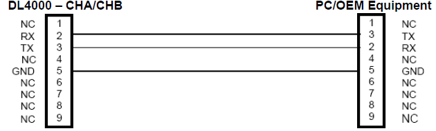
2. Online Cable DL4000-CHA – No Handshaking
3. Online Cable DL4000-CHB – No Handshaking
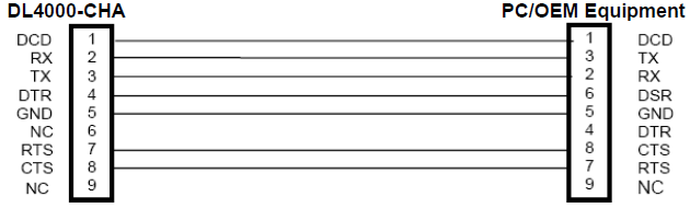
4. Online Cable DL4000-CHA RS-232C – With Handshaking
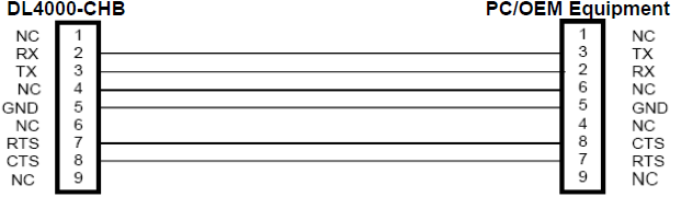
5. Online Cable DL4000-CHB RS-232 – With RTS/CTS Handshaking
6. Online Cable DL4000-CHA RS422/RS485
7. Online Cable DL4000-CHA RS422/RS485
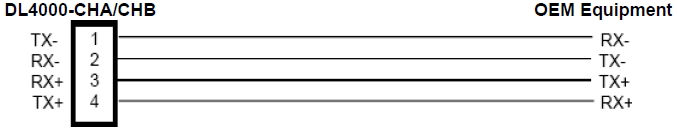
Note: 4 Pin Connectors are numbered from Left to Right
For RS485 Jumper Pins 1-2 and 3-4 for - and + wires
Configuration Software for the DL4000-DMX
After installing the latest EQ32 software and Running the Application the following screens will appear.
1. Select DL4000 MODELS
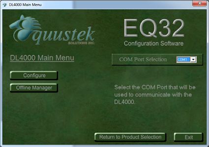
2. Select the COM PORT used to communicate with the DL4000
3. Click on Configure.
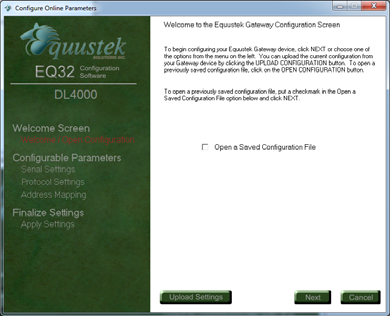
4. If you have a saved file check mark open saved configuration file if not just click on next.
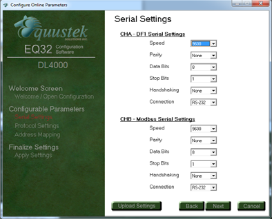
5. Set up the CHA – DF1 Serial Parameters (Baud, Parity, etc)
6. Set up the CHB – Modbus Serial Parameters (Baud, Parity, etc)
7. Setup/Change DF1 and Modbus Operating Parameters, also set your mapping table.
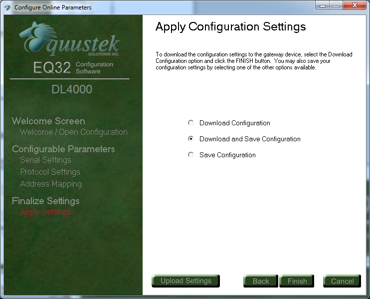
8. Select DOWNLOAD configuration or download and save configuration, to save the file for future use then click finish to transfer the Parameters to the DL4000-DMX once the download is complete press the reset button on the DL4000 unit.
DL4000-DMX-DF1/MODBUS
COMMUNICATION CONTROLLER APPLICATION NOTE
This application note contains information on the DL4000-DMX interface. The DL4000-DMX contains two modes
of operation, Modbus Master and Modbus Slave, which are selectable by the PC Configuration Software. The
latest version is available on the web at http://www.equustek.com.
The information contained in this application note is supplementary information specific to Modbus not contained in the regular User's Guide.
Master or Slave mode?
This application note is divided into two parts Modbus Master and Modbus Slave modes; they correspond to the mode the DL4000 is going to be on the Modbus Network, and which side DF1 or Modbus the commands will be initiated on.
Master mode is used when a device on the DH+ network is going to initiate all communications with one or many Modbus slave devices. Please Refer to DL4000-DMX/Modbus Master Application note..
Slave mode is used when a device on the Modbus network is going to initiate all communications with one or many SLC’s, PLC’s or other DH+ devices. Please Refer to DL4000-DMX/Modbus Slave Application note..
The application notes generally assume that a SLC or other DF1 device which can originate commands to Modbus via a DL4000 in master mode, or responding to Modbus commands via a DL4000 in slave mode. Only devices capable of transmitting or receiving DF1 Typed or Word Range commands can be used with the DL4000-DMX including SLC’s, MicroLogix’s, ControlLogix’s and HMIs as well as other intelligent devices.
Due to differences between DF1 and Modbus protocols and the universal design of the DL4000 there are differences between the lengths of messages, error handling and addressing which have to be carefully considered by the Systems Designer, Programmer and Installer.
CAUTION :
Incorrect configuration may result in unsafe operation, damage to equipment or safety hazard to personnel. Read the DL4000 User's Guide and the appropriate application notes carefully before putting a DL4000 on-line. The hardware and software must be fully tested off-line in a safe “TEST” environment prior to putting the unit online in an operational environment.
NOTES:
1. The unit that you have received can be configured as Modbus Master or Modbus Slave. Ensure that you understand and carefully follow the specific configuration procedures for the Modbus protocol.
2. There are significant differences between the configuration, programming and operational requirements of Modbus Master and Modbus Slave protocols.
3. If you configure the DL4000 for Modbus Master Operation it must be the only master on the Modbus network. A DF1 device originates commands to the DL4000-Modbus Master that then re-transmits them over Modbus to a Modbus Slave device.
4. Due to differences between DF1, Modbus and the hardware and software there are differences between the lengths of messages, error handling and addressing which have to be carefully considered by the Systems Designer, Programmer and Installer.
5. Additional literature regarding DF1, Modbus and PLC products can be obtained from Modicon and A-B.
Tel : (604) 266-8547
The information contained in this application note is supplementary information specific to Modbus not contained in the regular User's Guide.
Master or Slave mode?
This application note is divided into two parts Modbus Master and Modbus Slave modes; they correspond to the mode the DL4000 is going to be on the Modbus Network, and which side DF1 or Modbus the commands will be initiated on.
Master mode is used when a device on the DH+ network is going to initiate all communications with one or many Modbus slave devices. Please Refer to DL4000-DMX/Modbus Master Application note..
Slave mode is used when a device on the Modbus network is going to initiate all communications with one or many SLC’s, PLC’s or other DH+ devices. Please Refer to DL4000-DMX/Modbus Slave Application note..
The application notes generally assume that a SLC or other DF1 device which can originate commands to Modbus via a DL4000 in master mode, or responding to Modbus commands via a DL4000 in slave mode. Only devices capable of transmitting or receiving DF1 Typed or Word Range commands can be used with the DL4000-DMX including SLC’s, MicroLogix’s, ControlLogix’s and HMIs as well as other intelligent devices.
Due to differences between DF1 and Modbus protocols and the universal design of the DL4000 there are differences between the lengths of messages, error handling and addressing which have to be carefully considered by the Systems Designer, Programmer and Installer.
CAUTION :
Incorrect configuration may result in unsafe operation, damage to equipment or safety hazard to personnel. Read the DL4000 User's Guide and the appropriate application notes carefully before putting a DL4000 on-line. The hardware and software must be fully tested off-line in a safe “TEST” environment prior to putting the unit online in an operational environment.
NOTES:
1. The unit that you have received can be configured as Modbus Master or Modbus Slave. Ensure that you understand and carefully follow the specific configuration procedures for the Modbus protocol.
2. There are significant differences between the configuration, programming and operational requirements of Modbus Master and Modbus Slave protocols.
3. If you configure the DL4000 for Modbus Master Operation it must be the only master on the Modbus network. A DF1 device originates commands to the DL4000-Modbus Master that then re-transmits them over Modbus to a Modbus Slave device.
4. Due to differences between DF1, Modbus and the hardware and software there are differences between the lengths of messages, error handling and addressing which have to be carefully considered by the Systems Designer, Programmer and Installer.
5. Additional literature regarding DF1, Modbus and PLC products can be obtained from Modicon and A-B.
Contact Technical Support if you need further information or assistance.
Tel : (604) 266-8547
Or E-Mail : info@equustek.com
1.0 DL4000-DMX MODBUS MASTER MODE GENERAL
The DL4000-DMX can be configured as a Modbus network "Master". In this mode it enables SLC’s and other DF1
devices to initiate various commands to read and write coils, inputs and registers of slave devices on a Modbus
network.
The Modbus interface can be set for RS232 or RS422/RS485. Typical DF1 capable devices that can communicate with Modbus via the DL4000 include such devices as PLC3s, PLC5s, SLC500s, MicroLogix’s, PCs, HMIs and other intelligent OEM devices. (Now referred to as PLC’s in this document) Communication between Modbus and the DL4000 must be initiated from the DF1 device or PLC.
The DL4000 must be the only Master on the Modbus network and does not require a Modbus address. The DL4000 requires a unique DF1 station address number. The DL4000 can accept PLC3 Word Range Read/Write, PLC5 Typed Read/Write message commands, and SLC Typed Logical Read/Write.
The Destination Data Table Address or TAG is normally used to address a specific File and Word in another PLC. This address is interpreted by the DL4000 in a specific way and permits data to be mapped from a PLC and a Modbus slave device. This allows the PLC programmer to directly address a specific register in a Modbus slave device without any previous configuration being necessary in the DL4000.
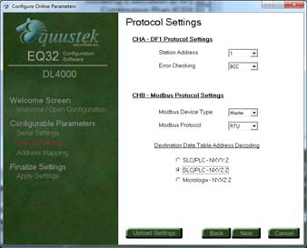
In the configuration software the type of PLC used is selected. See below.
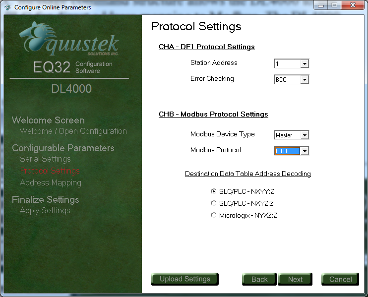 Modbus Parameters-EQ3Configuration software
Destination (Target) Data Table Address Decoding Options for PLC5 Type commands (Used by SLC’s and PLC’s):
Modbus Parameters-EQ3Configuration software
Destination (Target) Data Table Address Decoding Options for PLC5 Type commands (Used by SLC’s and PLC’s):
SLC’s OR PLC’s - (NXYY:Z)
Use this format if the SLC, PLC, or other device allows up to 999:9999 to be entered for the file and word. The file goes up to 999 and the word up to 9999.
• X – Registers or Coils
• 0 = 0X, 1 = 1X, 3 = 3X, 4 = 4X
• YY – Slave address
• 1 to 99
• Z – Register address
• 1 to 9999
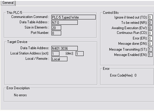
Example1:
N401:3036 will access register 43036 from Modbus Slave address 1.
N401:3036 • X = 4 (4X references),
YY = 01 (Slave address), Z = 3036 (Register address)
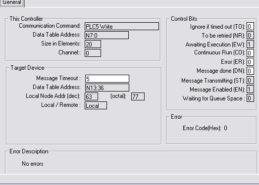
To read and write to slave devices on Modbus it is necessary to program the DF1 message instruction. This is an example of message command you may write using your PLC5 with the format NXYY:Z Your starting register address for this example is 3036. Your size in element is 20.
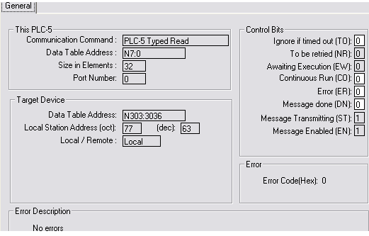
 Example2: N303:3036 will access register 33036 from Modbus Slave address 3
N303:3036
Example2: N303:3036 will access register 33036 from Modbus Slave address 3
N303:3036
X = 3 (3X references), YY = 03 (Slave address), Z = 3036 (Register address) For this example, we still have the format NXYY:Z. Your starting register address for this example is 3036. Your size in element is 32. In this case, the node address of my target device is 63 (77 in oct).
 Example3: B003:7 will access register 00007 from Modbus Slave address 3
B003:7
Example3: B003:7 will access register 00007 from Modbus Slave address 3
B003:7
X = 0 (0X references), YY = 03 (Slave address), Z = 7 (Register address) For this example, we still have the format BXYY:Z. Your starting register address for this example is 7. Your size in element is 32.

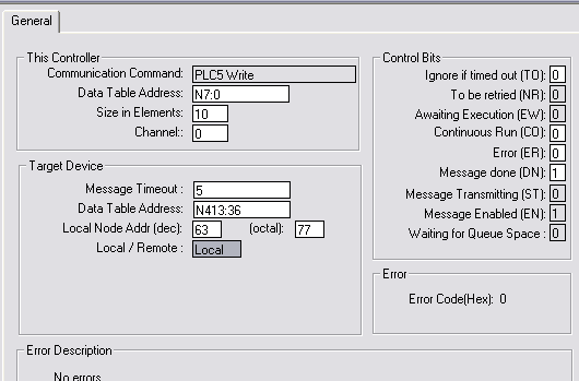
Example1: N413:36 will access register 43036 from Modbus Slave address 1. N413:36
X = 4 (4X references), Y = 1 (Slave address), Z:Z = 3:36 (Register address) NOTE: Z:Z cannot equal 0:0. The minimum value for Z:Z is 0:1. This is an example of message command you may write using your SLC5/04 with the format NXYZ:Z Your starting register address for this example is 3036. Your size in element is 10.
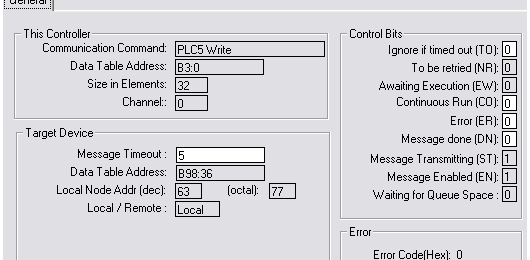
 Example2: B098:36 will access register 08036 from Modbus Slave address 9.
B098:36
Example2: B098:36 will access register 08036 from Modbus Slave address 9.
B098:36
X = 0 (0X references), Y = 9 (Slave address), Z:Z = 8:36 (Register address) This is an example of message command you may write using your SLC5/04 with the format NXYZ:Z Your starting register address for this example is 8036. Your size in element is 32. In this case, the node address of my target device is 63 (77 in oct).
• X – Registers or Coils
• 0 = 4X, 1 = 1X, 2 = 0X
• Y – Slave address
• 1 to 9
• Z:Z – Register address
• Z before the colon ‘:’ – Thousands digit
• 0 to 5
• Z after the colon ‘:’ – Ones to Hundreds digits
• 0 to 255
Example1 :
N013:36 will access register 43036 from Modbus Slave address 1. N013:36
X = 0 (4X references), Y = 1 (Slave address 1), Z:Z = 3:36 (Register address)
NOTE :
Z:Z cannot equal 0:0. The minimum value for Z:Z is 0:1. This is an example of message command you may write using your SLC5/04 with the format NXYZ:Z Your starting register address for this example is 3036. Your size in element is 20. In this case, the node address of my target device is 63 (77 in oct).
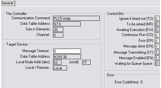
 Example2: N293:36 will access register 03036 from Modbus Slave address 9. N255:255 ONLY!
N013:36 ⇒ X = 2 (0X references), Y = 9 (Slave address 9), Z:Z = 3:36 (Register address)
NOTE: Z:Z cannot equal 0:0. The minimum value for Z:Z is 0:1.
This is an example of message command you may write using your SLC5/04 with the format NXYZ:Z Your starting register address for this example is 3036. Your size in element is 20. In this case, the node address of my target device is 63 (77 in oct).
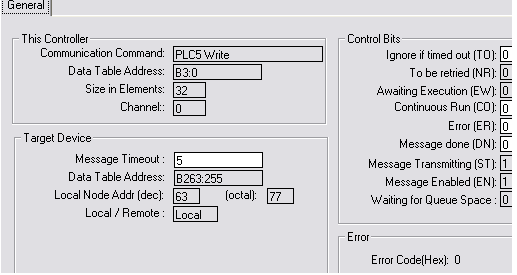
 Example3: B263:255 will access register 03255 from Modbus Slave address 6. N255:255 ONLY!
B263:255 ⇒ X = 2 (0X references), Y = 6 (Slave address 6), Z:Z = 3:255 (Register address)
Example3: B263:255 will access register 03255 from Modbus Slave address 6. N255:255 ONLY!
B263:255 ⇒ X = 2 (0X references), Y = 6 (Slave address 6), Z:Z = 3:255 (Register address)
NOTE: Z:Z cannot equal 0:0. The minimum value for Z:Z is 0:1.
This is an example of message command you may write using your SLC5/04 with the format NXYZ:Z Your starting register address for this example is 3255. Your size in element is 32. In this case, the node address of my target device is 63 (77 in oct).
The Modbus interface can be set for RS232 or RS422/RS485. Typical DF1 capable devices that can communicate with Modbus via the DL4000 include such devices as PLC3s, PLC5s, SLC500s, MicroLogix’s, PCs, HMIs and other intelligent OEM devices. (Now referred to as PLC’s in this document) Communication between Modbus and the DL4000 must be initiated from the DF1 device or PLC.
The DL4000 must be the only Master on the Modbus network and does not require a Modbus address. The DL4000 requires a unique DF1 station address number. The DL4000 can accept PLC3 Word Range Read/Write, PLC5 Typed Read/Write message commands, and SLC Typed Logical Read/Write.
The Destination Data Table Address or TAG is normally used to address a specific File and Word in another PLC. This address is interpreted by the DL4000 in a specific way and permits data to be mapped from a PLC and a Modbus slave device. This allows the PLC programmer to directly address a specific register in a Modbus slave device without any previous configuration being necessary in the DL4000.
1.1 ADDRESS MAPPING BETWEEN A-B AND MODBUS
The design of the DL4000 Modbus Master and the PLC message command structure allows the DL4000 to use the
contents of the Destination Data Table Address in the PLC for direct address mapping to Modbus. The DL4000
decodes the Destination DT Address to access to various Modbus Slave stations, commands and addresses. The
actual Modbus station number and addresses ranges that can be accessed depends on the PLC type, DF1 message
type and Programming software used.
In the configuration software the type of PLC used is selected. See below.
Modbus Parameters-EQ3Configuration software
SLC’s OR PLC’s - (NXYY:Z)
Use this format if the SLC, PLC, or other device allows up to 999:9999 to be entered for the file and word. The file goes up to 999 and the word up to 9999.
• X – Registers or Coils
• 0 = 0X, 1 = 1X, 3 = 3X, 4 = 4X
• YY – Slave address
• 1 to 99
• Z – Register address
• 1 to 9999
Example1:
N401:3036 will access register 43036 from Modbus Slave address 1.
N401:3036 • X = 4 (4X references),
YY = 01 (Slave address), Z = 3036 (Register address)
To read and write to slave devices on Modbus it is necessary to program the DF1 message instruction. This is an example of message command you may write using your PLC5 with the format NXYY:Z Your starting register address for this example is 3036. Your size in element is 20.
X = 3 (3X references), YY = 03 (Slave address), Z = 3036 (Register address) For this example, we still have the format NXYY:Z. Your starting register address for this example is 3036. Your size in element is 32. In this case, the node address of my target device is 63 (77 in oct).
X = 0 (0X references), YY = 03 (Slave address), Z = 7 (Register address) For this example, we still have the format BXYY:Z. Your starting register address for this example is 7. Your size in element is 32.
SLC’s OR PLC’s - (NXYZ:Z)
Use this format if the SLC, PLC, or other device allows up to 999:999 to be entered for the file and word.
The file goes up to 999 and the word up to 999.
• X – Registers or Coils
• 0 = 0X, 1 = 1X, 3 = 3X, 4 = 4X
• Y – Slave address
• 1 to 9
• Z:Z – Register address
• Z before the colon ‘:’ – Thousands digit
• 0 to 9
• Z after the colon ‘:’ – Ones to Hundreds digits
• 0 to 999
Example1: N413:36 will access register 43036 from Modbus Slave address 1. N413:36
X = 4 (4X references), Y = 1 (Slave address), Z:Z = 3:36 (Register address) NOTE: Z:Z cannot equal 0:0. The minimum value for Z:Z is 0:1. This is an example of message command you may write using your SLC5/04 with the format NXYZ:Z Your starting register address for this example is 3036. Your size in element is 10.
X = 0 (0X references), Y = 9 (Slave address), Z:Z = 8:36 (Register address) This is an example of message command you may write using your SLC5/04 with the format NXYZ:Z Your starting register address for this example is 8036. Your size in element is 32. In this case, the node address of my target device is 63 (77 in oct).
MicroLogix’s and SLC’s - (NXYZ:Z) Wrong order
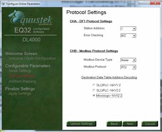
Use this format if the SLC, PLC, or other device allows up to 255:255 to be entered for the file and word.
The file goes up to 255 and the word up to 255.
• X – Registers or Coils
• 0 = 4X, 1 = 1X, 2 = 0X
• Y – Slave address
• 1 to 9
• Z:Z – Register address
• Z before the colon ‘:’ – Thousands digit
• 0 to 5
• Z after the colon ‘:’ – Ones to Hundreds digits
• 0 to 255
Example1 :
N013:36 will access register 43036 from Modbus Slave address 1. N013:36
X = 0 (4X references), Y = 1 (Slave address 1), Z:Z = 3:36 (Register address)
NOTE :
Z:Z cannot equal 0:0. The minimum value for Z:Z is 0:1. This is an example of message command you may write using your SLC5/04 with the format NXYZ:Z Your starting register address for this example is 3036. Your size in element is 20. In this case, the node address of my target device is 63 (77 in oct).
N013:36 ⇒ X = 2 (0X references), Y = 9 (Slave address 9), Z:Z = 3:36 (Register address)
NOTE: Z:Z cannot equal 0:0. The minimum value for Z:Z is 0:1.
This is an example of message command you may write using your SLC5/04 with the format NXYZ:Z Your starting register address for this example is 3036. Your size in element is 20. In this case, the node address of my target device is 63 (77 in oct).
NOTE: Z:Z cannot equal 0:0. The minimum value for Z:Z is 0:1.
This is an example of message command you may write using your SLC5/04 with the format NXYZ:Z Your starting register address for this example is 3255. Your size in element is 32. In this case, the node address of my target device is 63 (77 in oct).
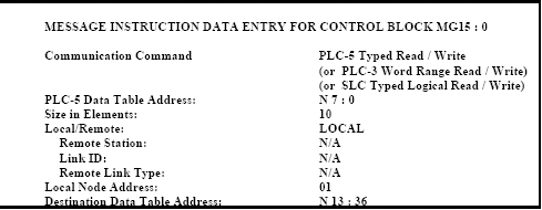
1.2 PLC/SLC/MicroLogix MESSAGE COMMAND
To read and write to slave devices on Modbus it is necessary to program the DF1 message instruction. You can use
either PLC-3, PLC-5 Word Range Read / Write, PLC-5 Typed Read / Write or SLC Type Logical Read/Writes.
 Using the SLC NXYZ:Z example above as the configuration causes the following:
Entering either a “PLC-5 Typed” or “SLC Typed Logical" in the "Communication Command" block of the message instruction to the DL4000 or an “N” as the Destination Data Table Address File type using a “PLC-3 Word Range” command will cause a the 4X Modbus registers to be accessed or function code of "03/16 (Read/Write) to be generated by the DL4000.
Enter the starting address of the A-B File: Word(s) to be used for read or write in the "PLC-5 Data Table Address" block of the message instruction.
Enter the number of words or registers to be transmitted in the "Size in Elements" field of the message function block. Enter the DL4000’s station address configured in the "Local Node Address" field.
The Modbus command, Modbus slave station address and Modbus start address are entered in the "Destination Data Table" field. See above sections on the decoding of the DDTA.
Check that the Modbus Slave Station address and Modbus Registers required can be entered into the specific PLC’s Destination Data Table Address field using PLC programming software.
1.2.1 MODBUS MESSAGE DATA LENGTH CONSIDERATIONS
Devices such as SLC’s can initiate PLC-5 Typed Read and Write commands to the DL4000 out their CH0. The
DL4000 then issues an appropriate Modbus read or write command to read or write the data to a Slave device on a
Modbus Network.
For example a SLC initiates a PLC-5 Type Read command using an N File type in the DDTA - this is translated to a Modbus Read Holding Register command (03). This command reads data from the Modbus Slave 4xxxx register address(es) specified in the DDTA and writes it to the file / word(s) specified in the PLC-5 Data Table Address. Conversely a PLC-5 Type Write command generates a Modbus Pre-set Multiple Holding Registers command (16) which reads data from the SLC file / word(s) specified and writes it to a Modbus Slave station's 4xxxx register(s).
DH+ TO MODBUS HOLDING REGISTERS (4X) EXAMPLES
1.3 COMMUNICATIONS SEQUENCE
The DL4000-DMX receives message commands from a PLC over its CHA/DF1 port, converts them to the
appropriate Modbus message and sends them out on its serial port. The Modbus Slave response is received,
translated into an appropriate DF1 response and then returned to the originating PLC.
Modbus Master/Slave protocol does not permit multiple messages on the Modbus network. The DL4000 processes one message at a time out of its Modbus port, although it can handle multiple requests from PLC’s, the programmer should ensure a response is received before initiating another request. The DL4000 unit will respond to the PLC with appropriate error messages in the event of detectable errors on Modbus such as timeouts.
Modbus Master/Slave protocol does not permit multiple messages on the Modbus network. The DL4000 processes one message at a time out of its Modbus port, although it can handle multiple requests from PLC’s, the programmer should ensure a response is received before initiating another request. The DL4000 unit will respond to the PLC with appropriate error messages in the event of detectable errors on Modbus such as timeouts.
1.4 MODBUS MESSAGE DATA LENGTH CONSIDERATIONS
The following shows the maximum number of holding registers that can be sent or received in a single Modbus
message when using the DL4000 gateway. The limits are because of the different structure of Modbus and A-B DF1
protocols, and also due to the internal memory structure of the DL4000.
• Up to 100 Modbus Holding Registers can be read in a single transaction
• Up to 100 Modbus Holding Registers can be written in a single transaction
Things to be added
• PLC-3 commands need to be added.
• Diagnostic commands.
• More Modbus Master examples.
o Show examples of reading and writing to 0X, 1X, 3X, 4X
2.0 DL4000-DMX MODBUS SLAVE MODE GENERAL
The DL4000-DMX Modbus Slave module facilitates communication between a Modbus Master and an Allen-
Bradley DF1 device. The DL4000 provides for serial communications to Modbus with RS232C, RS232 or
RS422/RS485 interface capabilities. Communication between Modbus and the DL4000 can only be initiated from a
Modbus Master (not from the DF1 side).
The Modbus serial port on the DL4000 is transparent to Modbus and does not require an address. The DF1 interface side of the DL4000 unit requires its own station address.
A Modbus Master can read and write to any SLC/PLC/ DF1 device that can handle PLC5 message commands without the need for any programming in the PLC, however the PLC addresses used must not be “protected" and the full range of addresses that the Modbus Master requires to read from or write to must have been previously created in the PLC's data Table. Modbus read and write bit/coil commands are used with A-B PLC Binary (B) files and Modbus read and write word/register commands are used with A-B PLC’s Integer (N) files.
2.1 MODBUS COMMAND CAPABILITIES
The DL4000-DMX firmware module is compatible with the following Modbus commands: -
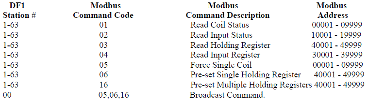
2.2 BROADCAST COMMAND
Modbus protocol uses the Broadcast command (i.e. commands 05, 06 and 16 with a station address of 00) to write to
all slave devices on a Modbus network simultaneously, no response is expected by the Master. Allen-Bradley DF1
protocol does not support Broadcast. DL4000’s can be configured to ignore or to execute Broadcasts. Broadcasting
is accomplished by splitting the command into separate messages for retransmission one at a time to each DF1
station within pre-configured range of stations. Because of the time taken to send out multiple DF1 messages,
Broadcasts commands are normally restricted to an absolute minimum range.
A PLC or other device at station address 00 cannot be addressed by Modbus read or write commands as 00 is normally the Broadcast command. DF1 station address 00 may be used as the station address for the DL4000.
A PLC or other device at station address 00 cannot be addressed by Modbus read or write commands as 00 is normally the Broadcast command. DF1 station address 00 may be used as the station address for the DL4000.
2.3 COMMUNICATIONS SEQUENCE
The DL4000 module receives a Modbus query on its asynchronous serial port, converts it into the appropriate DF1
message and sends it out its asynchronous DF1 port. The DF1 response is received, converted into the corresponding
Modbus response and sent back to the Modbus Master. Modbus protocol does not allow messages to be buffered so
the DL4000 processes one message at a time. The DL4000 unit will respond to the Modbus interface with the
appropriate Modbus exception codes in the event of detectable errors.
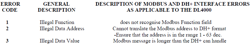
2.4 MODBUS EXCEPTION CODE RESPONSES
2.5 MODBUS MESSAGE DATA LENGTH CONSIDERATIONS
The following shows the maximum number of coils/registers that can be sent or received in a single Modbus
message. The limits are because of the different structure of Modbus and A-B DF1 protocols, and also due to the
internal memory structure of the DL4000. These values have only a limited relationship to the Modbus/DF1 address
mapping ranges configured in the DL4000.
• The max. Number of coils that can be read in a single transaction is 1600. (Normal Modbus allows 2000)
• The max. Number of registers that can be read in a single transaction is 100. (Normal Modbus allows 125)
• The max. Number of registers that can be written in a single transaction is 100. (Normal Modbus allows 100)
CAUTIONS:
1. Ensure that your communications program design prevents self-optimising Modbus Master Communications Programs (in some MMIs and Operator Interfaces) from requesting data in packets larger than the above limits.
2. Ensure that the Modbus program does not generate Modbus commands with addresses that can bridge across more than one of the address range entries configured in the DL4000.
3. Any of the above conditions could cause indeterminate errors.
2.6 MODBUS TO DF1 - GENERAL OVERVIEW
The DL4000 unit is transparent to valid Modbus commands addressed to station numbers corresponding to DF1
destination address. The DL4000 will only accept commands to DF1 station addresses 1 to 63 decimal. Modbus
commands using address 0 are broadcast commands and are handled differently by the DL4000.
After formatting and converting the Modbus message to DF1 protocol the command is sent out to the addressed DF1 (slave) device. If the station is inactive the query is disregarded. Each addressed slave station must be a unique address on Modbus or on the DF1 link i.e. do not duplicate an address used on the Modbus network with a station address on the DF1 side. If duplicate addresses exist then the situation will arise where two or more stations could accept the query resulting in multiple responses which would cause communications errors and perhaps writing to unintended destinations.
NOTE:
Special consideration should be given to the Modbus and DF1 addressing to avoid duplication of network addresses. Confusion could arise because A-B sometimes uses an "octal" addressing scheme for stations and Modbus uses "decimal". Ensure use of a common numbering scheme.
2.7 MODICON MODBUS TO A-B PLC ADDRESS MAPPING
The relationship between Modicon Modbus and Allen-Bradley PLC addresses is programmed by the user and is
stored in the DL4000's EEPROM. The DL4000 can be programmed for eight different address ranges. Each
Modicon address range that you wish to set-up may be mapped to a unique A-B address range. The length of the AB
field required is the same as that defined by the Modicon address range. All A-B files should be either Binary,
Integer or Floating Point files.
These A-B files must be created by the A-B PLC programmer to the full length required by the Modbus Address Translation and Mapping parameters specified. No logic is needed in the A-B PLC to respond to commands received from the Modbus network. To define how a range of Modicon addresses maps over to Allen-Bradley addresses, the user must enter the following configuration information:
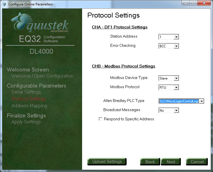
In the configuration software the type of PLC used is selected. See below Allen Bradley PLC type. In case you are requesting data from both SLC’s and PLC’s select SLC/MicroLogix/ControlLogix
 Modbus Parameters-EQ32 configuration.
These A-B files must be created by the A-B PLC programmer to the full length required by the Modbus Address Translation and Mapping parameters specified. No logic is needed in the A-B PLC to respond to commands received from the Modbus network. To define how a range of Modicon addresses maps over to Allen-Bradley addresses, the user must enter the following configuration information:
In the configuration software the type of PLC used is selected. See below Allen Bradley PLC type. In case you are requesting data from both SLC’s and PLC’s select SLC/MicroLogix/ControlLogix
Modbus Parameters-EQ32 configuration.
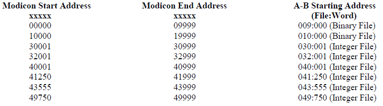
2.7.1 DEFINITION OF MODBUS SLAVE PARAMETER SCREEN
Modicon Start Address:
Specifies the starting address of a range of Modbus addresses that will be mapped to A-B.Valid entries are 00000 to 09999, 10000 to 19999, 30001 to 39999 and 40001 to 49999.
Modicon End Address:
Specifies the end address of a range of Modbus Addresses that will be converted to A-B. The range of entries is shown above.
A-B Starting Address:
Specifies the A-B PLC starting file number for the Modbus data. Valid entries are 001:000 to 999 : 999 (Sometimes files less than 8 are reserved) (ensure that data length does not exceed file boundary). NOTE: N7 and B3 are valid files!! Floating Point Checkbox: Used to Specify if the data is Modbus Floating point and to be written into Floating Point Files
Coils/discretes:
The bit address range of an A-B Binary file is 1000 words or 16,000 bits (i.e. 0 - 15,999 decimal). This means that one A-B file is more than sufficient to hold the largest Modbus coil address possible. An A-B binary file/bit address starts at bit 0 and the first “legal” Modbus coil address starts at 1, which means that normally the first Modbus coil address 00001 (or 10001) will correspond to bit 0 in A-B word 0. If a Modbus address of 00000 (or 10000) is entered in the Starting Address field it causes the first (legal) Modbus coil addresses i.e. bit 1 to correspond to an A-B file/word bit 1. This technique makes it easy to compare and match the Modbus and A-B memory maps, and easier to bit search the A-B program. When a Modbus coil /bit address is defined in the Start Address field i.e. 0XXXX or 1XXXX), then the first A-B Starting Address that can be used is Binary file 3 word 000 (B3:0).Registers/words:
The word address range of an A-B Integer file is 0 - 999 i.e., only 1000 words (registers). Therefore if a Modbus address range greater than 1000 registers is required, it is necessary to use more than one A-B Integer (N) file, which will require multiple configuration parameter entries. The first A-B address that can be used for 3xxxx and 4xxxx register/word transfers is an A-B Integer file at file/word address N7:0.Address Ranges:
The Modicon Address Range (i.e., Start Address less End Address), and the A-B Start Address selected, must not overflow the maximum A-B file address limit. This means that if A-B Starting Address of word 250 is used then the maximum register range for mapping must be 1000 minus 250, i.e. 750.2.7.2 MODICON TO AB ADDRESS MAPPING EXAMPLE
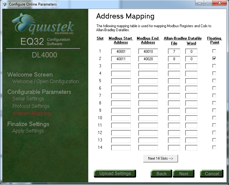
Example 1 Integer Files
Mapping Modicon registers 40001 to 40010 to A-B file N7:0 to N7:9
Or (registers 40001 to 40010 to A-B file N7:1 to N7:10) *** (See note)
Mapping Modicon registers 30011 to 30070 to A-B file N12:20 to N12:79
Or (registers 30011 to 30070 to A-B file N12:11 to N12:70) ***
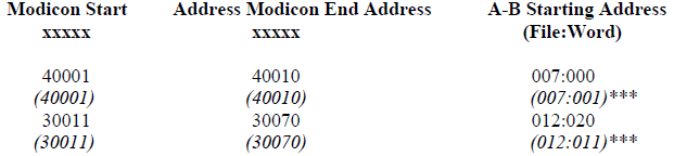
(***)Note:
This technique makes it easy to compare and match the Modbus and A-B memory maps, and easier to bit search the A-B program.
Example 2 Binary Files
Mapping Modicon coils 00001 to 00010 to A-B file B3/48 (binary file B3, bit 48) to B3/57
Or (coils 00001 to 00010 to A-B file B3/01 to B3/10)***
Mapping Modicon coil 00020 to A-B file B3/98
Or (coil 00020 to A-B file B3/20)***
Mapping Modicon coils 10031 to 10040 to A-B file B3/32 to B3/41
Or (coils 10031 to 10040 to A-B file B3/41 to B3/50)***
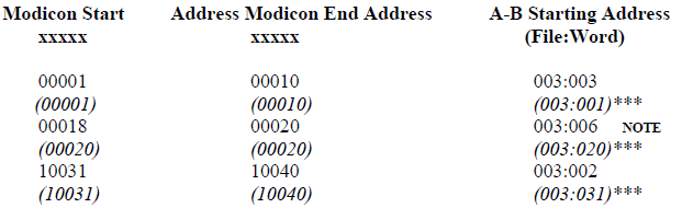
NOTE:
When mapping a Modicon coil to an A-B PLC bit that does not start at bit 0 of a word, an offset to bit 0 must be added.
Example 3 Floating Point Files
Mapping Modicon registers 40001 to 40002 to A-B file F8:0
Mapping Modicon registers 30001 to 30010 to A-B file F8:5 to F8:9
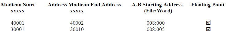
NOTE:
A-B Floating Point (F) values are 32 bits in length and require two Modbus registers for each floating point value.
NOTES:
1. The (Binary File) and (Integer File) text after the A-B File:Word address does not appear on the configuration screen and is provided here for reference only.
2. The A-B file corresponding to Modbus Coil addresses should have been previously configured in the PLC as a Binary (B) file and its size configured for the largest coil address.
3. The A-B file corresponding to Modbus Register addresses should have been previously configured in the PLC as an Integer (N) file and its size configured for the largest register address.
Mapping Modicon registers 40001 to 40010 to A-B file N7:0 to N7:9
Or (registers 40001 to 40010 to A-B file N7:1 to N7:10) *** (See note)
Mapping Modicon registers 30011 to 30070 to A-B file N12:20 to N12:79
Or (registers 30011 to 30070 to A-B file N12:11 to N12:70) ***
(***)Note:
This technique makes it easy to compare and match the Modbus and A-B memory maps, and easier to bit search the A-B program.
Example 2 Binary Files
Mapping Modicon coils 00001 to 00010 to A-B file B3/48 (binary file B3, bit 48) to B3/57
Or (coils 00001 to 00010 to A-B file B3/01 to B3/10)***
Mapping Modicon coil 00020 to A-B file B3/98
Or (coil 00020 to A-B file B3/20)***
Mapping Modicon coils 10031 to 10040 to A-B file B3/32 to B3/41
Or (coils 10031 to 10040 to A-B file B3/41 to B3/50)***
NOTE:
When mapping a Modicon coil to an A-B PLC bit that does not start at bit 0 of a word, an offset to bit 0 must be added.
Example 3 Floating Point Files
Mapping Modicon registers 40001 to 40002 to A-B file F8:0
Mapping Modicon registers 30001 to 30010 to A-B file F8:5 to F8:9
NOTE:
A-B Floating Point (F) values are 32 bits in length and require two Modbus registers for each floating point value.
NOTES:
1. The (Binary File) and (Integer File) text after the A-B File:Word address does not appear on the configuration screen and is provided here for reference only.
2. The A-B file corresponding to Modbus Coil addresses should have been previously configured in the PLC as a Binary (B) file and its size configured for the largest coil address.
3. The A-B file corresponding to Modbus Register addresses should have been previously configured in the PLC as an Integer (N) file and its size configured for the largest register address.
2.7.3 ADDRESS MAPPING LIMITATIONS AND PRACTICES
Modbus protocol generally permits a maximum of about 125 registers or 2000 coils to be read in a single transaction
(the maximum number is dependent on the Modbus driver). When specifying multiple address translation ranges
within the same type of Modbus address (either Oxxxx, 1xxxx, 3xxxx or 4xxxx) it is essential to establish a buffer
region of at least 125 registers or 2000 coils between each address type’s range. Failure to do this may allow a selfoptimising
MMI interface program to write (or read) data to/from two different areas of the Allen-Bradley PLC with
undesired and indeterminate results.
The examples above define a similar A-B word address to the Modbus start address which allows easier comparison between the Modbus A-B addresses used. For example a Modbus start address of 40001 can be represented in A-B PLC-5 file format by using A-B integer file N 40:001. Address mapping using this technique is recommended for a user’s convenience only, as it provides a very useful method for record-keeping, cross-reference and recognition. This technique is not mandatory and any Modbus address can be written to any A-B file.
When considering use of the above technique note that the first available open A-B file address for a PLC-5 controller is file 7. Modbus address 0xxxx cannot be displayed similarly in A-B format as A-B output file 0 should not be used. In this case for easy recognition use an A-B Binary file for Modbus output coils such as 9, 99, 999 or any other convenient file number is easily recognisable.
DL4000 firmware permits the entry of 00000 and 10000 values in the Modicon Start Address field even though strictly speaking these are not legal Modbus addresses. This feature allows a programmer to align an A-B Binary file bit 1 with the first legal Modbus Bit / Coil address 1. For example mapping Modicon Start Address 00000 to A-B Start Address (B) 003:000, or Modicon Start Address 10000 to A-B Start Address (B) 010:000 aligns Modbus bit 1 with A-B bit 1. The "B" for Binary file is implied but not displayed.
NOTES:
1. Enough space must have been configured and be available in the A-B file to contain the full range of Modbus addresses specified or it will cause over-writing existing A-B files and data.
2. Do not transmit Modbus messages to the DL4000 to read or write more than 1600 coils or 100 registers in a single Modbus read or write command.
3. Ensure that all A-B addresses specified have been created in the destination PLC.
4. Set all unused Modbus to A-B addresses to zero.