DL2000
User Manual
Revision 1.01 – April 21, 2004
Equustek Solutions, Inc.
Suite 815, 1200 W73rd Ave.
Vancouver, BC, Canada
V6P 6G5
Toll Free: 888-387-3787
www.equustek.com
Table of Contents
1.0 DL2000 General Operation & Applications
The DL2000 communication controller is a 110/220V AC powered freestanding CSA/UL approved which provides a RS232/RS422/RS485 serial link to A-B’s DH+ or RIO networks.
The DL2000 has two communication ports. Channel A is designed to connect to you industrial network, either A-B’s DH+ or RIO networks. Channel B is used to connect to your serial
device, such as PC’s, HMI/MMI’s or PLC’s. The protocol used depends on which flavour (model) of the DL2000 you have ordered.
Channel B has the capabilities of RS232C, RS422, and RS485.
Configuration of the operating parameters is done quickly and easily by the DL32-FREEstanding windows based software shipped with the unit or available on the Equustek
Website.
Currently there are three standard DL2000 products available to allow access to A-B’s DH+ network; also many other customized ASCII protocol interfaces have been done. Contact
Equustek Solutions to see if the DL2000 is the correct device for your communication needs.
The DH+ version of the DL2000 product line is as follows :
The DL2000-CMX is a two port device that bridges your Modicon Modbus devices to ones on a DH+ network. The Modbus model can either be used as Modbus Master or Slave as well as having both Modbus ASCII and RTU protocols.
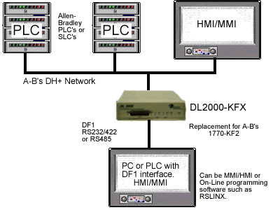
The DL2000-KFX is a two port device that allows your DF1 devices (either Full or Half Duplex protocols) to ones on a DH+ network. The DF1 model is a direct replacement for the 1770-KF2 and allows your PCs or Laptops access to any node on the DH+ network.
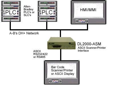
The DL2000-ASM interfaces Serial ASCII devices (Scanners/Printers) to SLC’s or other devices on A-B's DH+ network.
2.0 Hardware Specifications
CHA can be configured for DH+/RIO speeds of 57.6, 115.2 and 230.4 KBaud.
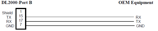
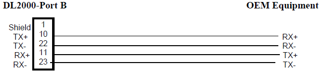
CHB has full RS232C, as well as both RS422 4 wire and RS485 2 wire modes. CHB has the ability of being configured with asynchronous speeds upto 57.6 KBaud. CHB has two physical
connections, a DB 25 Male and a configurable 5 pin phoenix (jumper configurable for RS232/RS422-RS485).
Currently industry standard protocols of DF1, Modbus, and ASCII are the supported. Many custom protocols for different Variable Speed Drives, Weight Scales and other OEM devices
have been implemented. Both CRC 16 and BCC error checking can be implemented; custom error checking can be added at the customer’s request.
Simple Parameter Configuration using menu driven Windows (95/98/ME/XP/NT/2000) based Program via RS-232 Cable.
Configuration and Reset Pushbuttons to setup online configuration parameters and do a full Hardware Reset
Operating Parameters are stored in Non-Volatile Serial EEPROM.
The DL2000 uses FLASH upgradeable firmware from the configuration Software.
Green communication LED’s for each communication channel indicates activity and status.
Red ERR Led indicates communication problems
Green POWER LED indicates power on.
3.0 DL2000-Hardware Layout

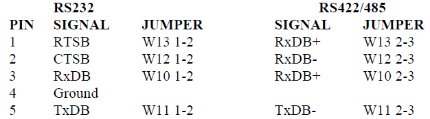
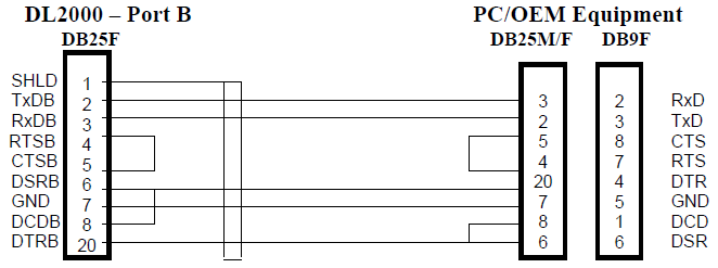
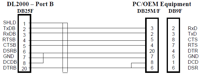
- 25 pin DB25M PORT B connector for asynchronous communications (CHB)
- 2 green CHAN 1 LEDs indicate the status of CHA (DH+/RIO)
- 2 green CHAN 2 LEDs indicate the status of PORT B (CHB-Asynchronous)
- Red ERR LED which indicates communication problems
- Green POWER LED indicates supply power
- RESET Pushbutton does a full system reset to put the unit on-line)
- CFG (Configure) Pushbutton puts the unit into the off-line manager mode
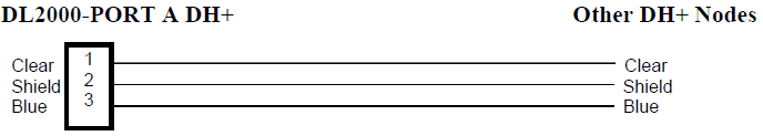
- PORT A (CHA-DH+ or RIO) 3 pin Screw terminal (Phoenix Type)
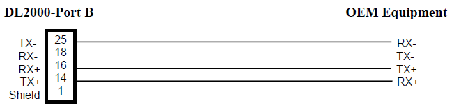
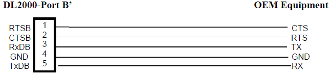
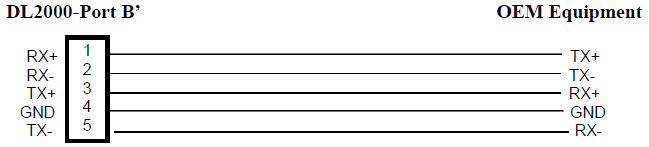
- PORT B’ (CHB-Asynchronous) 5 pin Screw terminal (Phoenix Type)
4.0 Mode of Operation
The Reset pushbutton automatically puts the DL2000 into Online mode.
DL OFF-LINE FLASH MANAGER Version 1.21 - 00/06/07
(c) Equus Technologies Inc. 1999-2000
1 - Restore EEPROM to Factory settings
2 - WRITE new Firmware Text file
3 - Memory DUMP
4 - OFF-LINE Diagnostic Tests
5 - DEBUG Mode
6 - Display FIRMWARE Version
7 - Go ONLINE
MAKE SELECTION (1-7) -
ERASING FLASH, PLEASE WAIT...
SEND FIRMWARE TEXT FILE NOW...
Once the message to send the firmware appears then either click on the “Burn Flash System File” button to select the .txt file to send, or send the Text File under HyperTerminal.
Wait for a “FIRMWARE LOAD/BURN COMPLETED A-OK!” message to appear.
5.0 Switch and LED Indicator Functions
The Configure pushbutton takes the DL2000 out of On-Line operation mode and puts it in the OFF-LINE Flash Manager mode. The OFF-LINE FLASH Manager mode also allows for configuration parameters to be downloaded from or uploaded to the Windows based configuration software (DL32-FREEstanding). When this mode has been entered the ERR and CHAN 2 OUT LED’s will be on. To put the unit back On-line it is necessary to either press the Reset or cycle the power supplied to the DL2000.
- LED
- STATUS
- PWR
- Green Continuously
- ERR
- Green for 0.5 seconds
- CHAN 2 OUT
- Green for 0.5 seconds
- CHAN 2 IN
- Green for 0.5 seconds
- CHAN 1 OUT
- Green for 0.5 seconds
- CHAN 1 IN
- Green for 0.5 seconds
- LED
- Description of Operation
- PWR
- Green Indicates Power is being supplied to the DL2000.
- CHAN 1 IN
- On when a specific message is directed to PORT A.
- CHAN 1 OUT
- On when a specific message is directed out PORT A.
- CHAN 2 IN
- On when a specific message is directed to CHB (Port B or B’).
- CHAN 2 OUT
- On when a specific message is directed out CHB (Port B or B’).
- ERR
- Flashes RED for about 0.5 secs when a NAK (Negative Acknowledgement) is received on CHB or all transmit and receive buffers are full. Will also flash at approximately 1Hz when a duplicate DH+ node is detected.
- LED Pattern
- Description of Problem
- ALL LED’s
Flashing ON & OFF - The flash has not be burnt properly and the A-OK was not transmitted. Please reburn the flash with the correct text file. Contact Customer Support for help.
- ALL LED’s
ON Solid - The OFF-LINE FLASH has been corrupted. A new Flash Chip has to be supplied by the factory. Please contact Customer support.
- Start-up Sequence
keeps repeating. - The DL2000 EEPROM is corrupt.. Please Restore to Factory Settings (See Section 1.1) and then reconfigure the unit.
- LED Pattern
- Description of Operation
- CHAN 2 OUT &
ERR - OFF-LINE FLASH Manager/Configuration Parameter
Download/Upload and Hardware Diagnostics Testing Mode - CHAN 2 IN &
CHAN 2 OUT &
ERR - Offline Debug Mode
6.0 DL2000 Wiring Diagrams and Jumpers
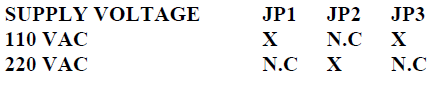
- N.C means Not Connected – X has a 0 Ohm resister for Model 1 or a 2 prong shunt for Model 2.
- No selection required for 50/60Hz
- 110 VAC cable is supplied with unit and is wired as follows:Green is Ground, Black is Live (Hot) and White is Neutral.
(JP1, JP2 and JP3 position do not matter)
Note: REMOVE AC Power Cord First
7.0 DL2000 DH+ Networking Applications
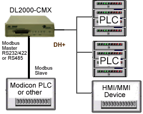
The Modbus Master can communicate with any Slave device on the Modbus Slave network and any DH+ devices capable of sending PLC3 or PLC5 message commands. Modbus and DH+ addresses must not be duplicated (convert to the same radix) or the Master will receive two responses. The DL2000 can be any station number on DH+ including Station 00 (not used on Modbus).
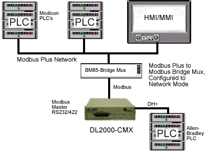
PLCs and HMI/MMIs etc. on Modbus Plus can be programmed to communicate with PLC5s, SLC5/04s and
HMI/MMIs on DH+, i.e. any devices capable of handling PLC-5 Type message commands.