DL3500-DH+/MODBUS
COMMUNICATION CONTROLLER APPLICATION NOTE
PDF Download
This application note contains information on the DL3500-Modbus to DH+ interface. The DL3500 model contains
two modes of operation, Modbus Master and Modbus Slave, which are selectable by the PC Configuration Software.
The latest version is available on the web at http://www.equustek.com/downloads.html
The information contained in this application note is supplementary information specific to Modbus not contained in
the regular User's Guide.
Master or Slave mode?
This application note is divided into two parts, Modbus Master and Modbus Slave modes; they correspond to the mode the DL3500 is going to be on the Modbus Network, and which side either DH+ or Modbus the commands will be initiated on.
Master mode is used when a device on the DH+ network is going to initiate all communications with one or many Modbus slave devices. Please Refer to DL3500-DH+/Modbus Master Application note.
Slave mode is used when a device on the Modbus network is going to initiate all communications with one or many SLC’s, PLC’s or other DH+ devices. Please Refer to DL3500-DH+/Modbus Slave Application note.
The application notes generally assume that a SLC or other DH+ device which can originate commands to Modbus via a DL3500 in master mode, or responding to Modbus commands via a DL3500 in slave mode. Only devices capable of transmitting DH+ message commands in PLC5 (or PLC3) format and able to receive DH+ message commands in PLC5 format can be used with the DL3500-Modbus/DH+ including SLC’s, MicroLogix’s, ControlLogix’s and HMIs as well as other intelligent devices.
Due to differences between DH+ and Modbus protocols and the universal design of the DL3500 there are differences between the lengths of messages, error handling and addressing which have to be carefully considered by the Systems Designer, Programmer and Installer.
CAUTION:
Incorrect configuration may result in unsafe operation, damage to equipment or safety hazard to personnel. Read the DL3500 User's Guide and the appropriate application notes carefully before putting a DL3500 on-line. The hardware and software must be fully tested off-line in a safe “TEST” environment prior to putting the unit on-line in an operational environment.
The Modbus Master Application notes contain configuration information for the DL3500-DH-485 protocol and should be used in conjunction with the DL3500 User's Guide.
The Modbus Master Application notes contain configuration information for the DL3500-DH-485 protocol and should be used in conjunction with the DL3500 User's Guide.
NOTES:
1. The unit that you have received can be configured as Modbus Master or Modbus Slave. Ensure that you understand and carefully follow the specific configuration procedures for the Modbus protocol.
2. There are significant differences between the configuration, programming and operational requirements of the Modbus Master and Modbus Slave protocols.
3. If you configure the DL3500 for Modbus Master Operation it must be the only master on the Modbus network. A station on DH+ originates commands to the DL3500-DH+ Modbus Master that then re-transmits them over Modbus to a Modbus Slave device. Other intelligent DH+ devices capable of initiating DH+ messages in PLC5 (or PLC3) format and able to receive PLC5 message commands could also be used as the DH+ “master”.
4. Be sure to fully test the hardware and software off-line to ensure that you understand its configuration and operation. Prior to putting the DL3500 on-line in an production process, the operation of the complete system should be fully tested on-line in a safe "test" environment.
5. Due to differences between DH+ and Modbus hardware and software, there are differences between the lengths of messages, error handling and addressing which have to be carefully considered by the Systems Designer, Programmer and Installer.
6. Additional literature regarding DH+, Modbus and PLC products can be obtained from Modicon and A-B. Suggested reference materials for A-B DH+ protocol is shown in section 1.7 of the User's Guide.
CAUTION:
Incorrect configuration may result in unsafe operation, damage to equipment or safety hazard to personnel.
Read the DL3500 User's Guide and the appropriate application notes carefully before putting a DL3500 on-line. The DL3500 hardware and software must be fully tested off-line in a safe “TEST” environment prior to putting the unit on-line in an operational environment.
TECHNICAL SUPPORT
The information contained in this application note is for the Modbus Master protocol only, and is supplementary to the information in the User's Guide. To use the DL3500 in Modbus Slave Mode follow the procedures in the Modbus Slave application notes. There are significant differences between the configuration, programming and operational requirements of Modbus Master and Modbus Slave protocols.
Master or Slave mode?
This application note is divided into two parts, Modbus Master and Modbus Slave modes; they correspond to the mode the DL3500 is going to be on the Modbus Network, and which side either DH+ or Modbus the commands will be initiated on.
Master mode is used when a device on the DH+ network is going to initiate all communications with one or many Modbus slave devices. Please Refer to DL3500-DH+/Modbus Master Application note.
Slave mode is used when a device on the Modbus network is going to initiate all communications with one or many SLC’s, PLC’s or other DH+ devices. Please Refer to DL3500-DH+/Modbus Slave Application note.
The application notes generally assume that a SLC or other DH+ device which can originate commands to Modbus via a DL3500 in master mode, or responding to Modbus commands via a DL3500 in slave mode. Only devices capable of transmitting DH+ message commands in PLC5 (or PLC3) format and able to receive DH+ message commands in PLC5 format can be used with the DL3500-Modbus/DH+ including SLC’s, MicroLogix’s, ControlLogix’s and HMIs as well as other intelligent devices.
Due to differences between DH+ and Modbus protocols and the universal design of the DL3500 there are differences between the lengths of messages, error handling and addressing which have to be carefully considered by the Systems Designer, Programmer and Installer.
CAUTION:
Incorrect configuration may result in unsafe operation, damage to equipment or safety hazard to personnel. Read the DL3500 User's Guide and the appropriate application notes carefully before putting a DL3500 on-line. The hardware and software must be fully tested off-line in a safe “TEST” environment prior to putting the unit on-line in an operational environment.
DDL3500-DH+ MODBUS MASTER TO A-B DH+ CONFIGURATION
Use this option when the DL3500 is required to be the master on a Modbus network.The Modbus Master Application notes contain configuration information for the DL3500-DH-485 protocol and should be used in conjunction with the DL3500 User's Guide.
DL3500-DH+ MODBUS SLAVE TO A-B DH+ CONFIGURATION
Use this protocol when the DL3500 is required to be a slave device on a Modbus network.The Modbus Master Application notes contain configuration information for the DL3500-DH-485 protocol and should be used in conjunction with the DL3500 User's Guide.
NOTES:
1. The unit that you have received can be configured as Modbus Master or Modbus Slave. Ensure that you understand and carefully follow the specific configuration procedures for the Modbus protocol.
2. There are significant differences between the configuration, programming and operational requirements of the Modbus Master and Modbus Slave protocols.
3. If you configure the DL3500 for Modbus Master Operation it must be the only master on the Modbus network. A station on DH+ originates commands to the DL3500-DH+ Modbus Master that then re-transmits them over Modbus to a Modbus Slave device. Other intelligent DH+ devices capable of initiating DH+ messages in PLC5 (or PLC3) format and able to receive PLC5 message commands could also be used as the DH+ “master”.
4. Be sure to fully test the hardware and software off-line to ensure that you understand its configuration and operation. Prior to putting the DL3500 on-line in an production process, the operation of the complete system should be fully tested on-line in a safe "test" environment.
5. Due to differences between DH+ and Modbus hardware and software, there are differences between the lengths of messages, error handling and addressing which have to be carefully considered by the Systems Designer, Programmer and Installer.
6. Additional literature regarding DH+, Modbus and PLC products can be obtained from Modicon and A-B. Suggested reference materials for A-B DH+ protocol is shown in section 1.7 of the User's Guide.
CAUTION:
Incorrect configuration may result in unsafe operation, damage to equipment or safety hazard to personnel.
Read the DL3500 User's Guide and the appropriate application notes carefully before putting a DL3500 on-line. The DL3500 hardware and software must be fully tested off-line in a safe “TEST” environment prior to putting the unit on-line in an operational environment.
Contact Technical Support if you need further information or assistance.
TECHNICAL SUPPORT
Tel : (604) 266-8547
Or E-Mail : info@equustek.com
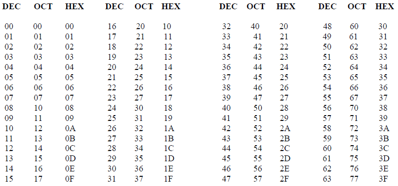
The following table provides a reference between the different radixes used for your reference
DECIMAL TO OCTAL TO HEXADECIMAL ADDRESS CONVERSION TABLE
APPLICATION NOTE
DL3500-Modbus/DH+ - MASTER PROTOCOL
The information contained in this application note is for the Modbus Master protocol only, and is supplementary to the information in the User's Guide. To use the DL3500 in Modbus Slave Mode follow the procedures in the Modbus Slave application notes. There are significant differences between the configuration, programming and operational requirements of Modbus Master and Modbus Slave protocols.
INDEX FOR MODBUS MASTER MODE
1.1 ADDRESS MAPPING BETWEEN A-B AND MODBUS
1
1.1.1 DESTINATION DATA TABLE ADDRESS FORMAT
3
1.2.1 DH+ MESSAGE COMMANDS
4
1.2.2 MODBUS COMMANDS
4
1.2.3 PLC-3 WORD RANGE COMMANDS (PLC-3’s and 5’s)
4
1.2.3.1 MODBUS DIAGNOSTICS COMMANDS
5
1.2.4 PLC-5 TYPED R/W & WORD RANGE R/W (PLC-5’s and SLC’s)
5
1.2.4.1 PLC5 TYPED COMMANDS USING NXYY:Z DECODE
5
1.2.4.2 PLC5 TYPED COMMANDS USING NXYZ:Z DECODE
6
1.2.4.3 PLC5 TYPED COMMANDS USING NYXZ:Z DECODE
6
1.2.4.4 MODBUS DIAGNOSTIC COMMANDS
7
1.2.5 BROADCAST COMMAND
4
1.3 DH+ MESSAGE COMMAND
4
1.3.1 A-B TO MODBUS EXAMPLES
4
1.3.1.1 PLC-3 WORD RANGE COMMANDS
9
1.3.1.2 PLC-5 TYPED COMMANDS (NXYY:Z)
9
1.3.1.3 PLC-5 TYPED COMMANDS (NXYZ:Z)
10
1.3.1.4 PLC-5 TYPED COMMANDS (NYXZ:Z)
10
1.4 COMMUNICATIONS SEQUENCE
11
1.5 MODBUS MESSAGE DATA LENGTH CONSIDERATIONS
11
1.6 MODBUS MASTER USING BM85 MODBUS PLUS / MODBUS BRIDGE MUX_
11
1.7 DH+ AND MODBUS - GENERAL
11
2.1 MASTER TO MODBUS SLAVE NETWORK
12
2.2 MASTER TO MODBUS PLUS VIA BM85 MODBUS BRIDGE
12
1.0 GENERAL
The DL3500 can be configured as a Modbus network "Master". In this mode it enables SLC’s and other devices on
a DH+ network to initiate various commands to read and write coils, inputs and registers of slave devices on a
Modbus network. The Modbus interface can be set for RS232 or RS422/RS485. Typical DH+ stations that can
communicate with Modbus via the DL3500 include devices such as PLC3s, PLC5s, SLC5/04s, PCs, HMIs and
other intelligent OEM devices. (Now referred to as PLC’s in this document)
Communication between Modbus and the DL3500 must be initiated from a DH+ PLC.
The DL3500 must be the only Master on the Modbus network and does not require a Modbus address. The DL3500 is an active station on DH+ and requires a unique DH+ station address number. The DL3500 can accept PLC3 Word Range Read/Write or PLC5 Typed Read/Write message commands from any station on the DH+ network.
The Destination Data Table Address or TAG is normally used to address a specific File and Word in another PLC on the network. This address is interpreted by the DL3500 in a specific way and permits data to be mapped from a PLC and a Modbus slave device. This allows the PLC programmer to directly address a specific register in a Modbus slave device without any previous configuration being necessary in the DL3500.
 Destination (Target) Data Table Address Decoding Options for Allan-Bradley PLC5 Type commands (Used by
SLC’s and PLC’s):
Destination (Target) Data Table Address Decoding Options for Allan-Bradley PLC5 Type commands (Used by
SLC’s and PLC’s):
PLC’s and SLC’s - (NXYY:Z)
Use this format if the SLC, PLC, or other device allows up to 999:9999 to be entered for the file:word.
• X – Registers or Coils
• 0 = 0X, 1 = 1X, 3 = 3X, 4 = 4X
• YY – Slave address
• 1 to 99
• Z – Register address
• 1 to 9999
Example: N41:3036 will access register 43036 from Modbus Slave address 1.
SLC’s - (NXYZ:Z)
Use this format if the SLC, PLC, or other device allows up to 999:999 to be entered for the file:word.
• X – Registers or Coils
• 0 = 0X, 1 = 1X, 3 = 3X, 4 = 4X
• Y – Slave address
• 1 to 9
• Z:Z – Register address
• Z before the colon ‘:’ – Thousands digit
• 0 to 9
• Z after the colon ‘:’ – Ones to Hundreds digits
• 0 to 999
Example: N413:36 will access register 43036 from Modbus Slave address 1.
NOTE: Z:Z cannot equal 0:0. The minimum value for Z:Z is 0:1.
MicroLogix’s and SLC’s - (NYXZ:Z)
Use this format if the SLC, PLC, or other device allows up to 255:255 to be entered for the file:word.
• Y – Slave address
• 0 = slave address 1, 1 = slave address 2, 2 = slave address 3
• X – Registers or Coils
• 0 = 0X, 1 = 1X, 3 = 3X, 4 = 4X
• Z:Z – Register address
• Z before the colon ‘:’ – Thousands digit
• 0 to 9
• Z after the colon ‘:’ – Ones to Hundreds digits
• 0 to 255
Example: N43:36 will access register 43036 from Modbus Slave address 1.
NOTES:
1. Z:Z cannot equal 0:0. The minimum value for Z:Z is 0:1.
2. Slave address 3 cannot access registers or coils above 5255.
For more information about using PLC-5 Typed Commands with the decoding formats shown above, refer to section 1.2.4 of this manual.
When a PLC is communicating with other devices over the DH+ network, the destination data table address (DDTA) has different meanings depending on whether it is communicating with another PLC or if it is communicating with a DL3500 Modbus Master. Below are descriptions of the different meanings for the DDTA.
The usual format of the destination data table address (DDTA) is: T F : e
T, F, and e are explained below.
Communicating with another PLC on the DH+ network
• T = File Type (O = output, I = input, B = binary, N = integer, etc.)
• F = File Number (0 - 63, 0-255, 0 - 999, or 0 - 9999) *
• e = Word Number (0 - 255, 0 - 999 or 0 – 9999) *
Communicating with a DL3500 Modbus Master on the DH+ network using PLC-3 commands
Data and Control Functions
• T = Modbus Command (B, N, S, F)
• F = Modbus Slave Address (1 - 255)
• e = Modbus Coil/Register (1 - 9999)Diagnostic Functions (Dxyyy:zzzz)
• T = Modbus Command (D)
• F = Sub-function Command / Slave Address (xyyy)
• e = Sub-function Command / Data (zzzz)
For more details about mapping the data and control functions and the diagnostic functions using PLC-3 commands, see section 1.2.3
Communicating with a DL3500 Modbus Master on the DH+ network using PLC-5 commands Data and Control Functions (includes Diagnostic Function)
• T = Not used **
• F = PLC-5 Decoding Format (NXYY:Z, NXYZ:Z, or NYXZ:Z Format)
• e = PLC-5 Decoding Format (NXYY:Z, NXYZ:Z, or NYXZ:Z Format)
For more details about mapping the data and control functions and the diagnostic functions using PLC-5 commands, see sections 1.1 and 1.2.4
* Depends on PLC type.
** To avoid errors when downloading your program to the PLC, a file type is needed so that a legal format for the DDTA is used.
The DL3500-DH+ set to Modbus Master Mode can generate Modbus protocol functions on receipt of the following DH+ message commands:
• PLC-3 Word Range Read or Word Range Write Commands
• PLC-5 Typed Read or Typed Write Commands
• PLC-5 Word Range Read and Writes
A-B PLCs can generate the following commands:
• SLC’s PLC-5 Typed Read/Write Commands
• PLC-3 PLC-3 Word Range Read/Write Commands
• PLC-5 PLC-3 Word Range Read/Write Commands and PLC-5 Typed Read/Write Commands
MODBUS DATA AND CONTROL COMMANDS USING PLC-3 WORD RANGE READ / WRITE COMMANDS
On receiving a PLC-3 Word Range Read or Word Range Write Message Command (MC) a DL3500 Modbus Master decodes the command’s Destination Data Table Address (DDTA) File type (character). Then, dependent on whether the DH+ message is a read or a write it can generate the appropriate Modbus command as shown in the table below.
 Note:
Note:
For Modbus command 05, set the first word of data in the PLC data table to FF00 (hex) to turn the coil ON and 0000 to turn the coil OFF.
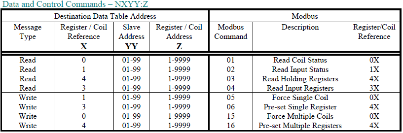
MODBUS DATA AND CONTROL COMMANDS USING PLC-5 TYPED READ / WRITE COMMANDS
On receiving a PLC-5 Typed Read or Word Range Write Message Command (MC) a DL3500-DH+ Modbus Master decodes the command’s Destination Data Table Address (DDTA) File type (character). Then, depending on whether the DH+ message is a read or a write command, it can generate the appropriate Modbus command as shown below.
 Note: Leading zeros in the Destination Data Table Address can be left out.
 Note:
Note:
1. Leading zeros in the Destination Data Table Address can be left out.
2. Register/Coil Address
• Z before the colon ‘:’ – Thousands digit
• Z after the colon ‘:’ – Ones to Hundreds digits
 Note:
Note:
1. Leading zeros in the Destination Data Table Address can be left out.
2. Register/Coil Address
• Z before the colon ‘:’ – Thousands digit
• Z after the colon ‘:’ – Ones to Hundreds digits
• Register and coil addresses range from 1-255, 1000-1255, 2000-2255, etc.
3. Slave Address
• 0 = slave address 1, 1 = slave address 2, 2 = slave address 3 4. Slave address 3 cannot access registers or coils above 5255.
Note: This is not supported for section 1.2.4.3 PLC-5 Typed commands using the NYXZ:Z decode option.
Examples
1. Integer - Writing to Modicon registers 40001 to 40010 in slave 5
2. Integer - Reading from Modicon registers 32201 to 32205 in slave 21
3. Binary - Writing to Modicon coil 00010 in slave 3
4. Binary - Writing to Modicon coils 00021 to 00036 in slave 6
5. Binary - Reading from Modicon coils 10101 to 10132 in slave 15
 Note :
When mapping binary files using Modbus commands 01, 02, and 15, the DL3500 Modbus Master maps 16 consecutive coils for every 1 element. Therefore 2 elements will map 32 consecutive coils.
Examples
1. Integer - Writing to Modicon registers 40001 to 40010 in slave 5
2. Integer - Reading from Modicon registers 32201 to 32205 in slave 21
3. Binary - Writing to Modicon coil 00010 in slave 3
4. Binary - Writing to Modicon coils 00021 to 00036 in slave 6
5. Binary - Reading from Modicon coils 10101 to 10132 in slave 15
Note :
When mapping binary files using Modbus commands 01, 02, and 15, the DL3500 Modbus Master maps 16 consecutive coils for every 1 element. Therefore 2 elements will map 32 consecutive coils.
Communication between Modbus and the DL3500 must be initiated from a DH+ PLC.
The DL3500 must be the only Master on the Modbus network and does not require a Modbus address. The DL3500 is an active station on DH+ and requires a unique DH+ station address number. The DL3500 can accept PLC3 Word Range Read/Write or PLC5 Typed Read/Write message commands from any station on the DH+ network.
The Destination Data Table Address or TAG is normally used to address a specific File and Word in another PLC on the network. This address is interpreted by the DL3500 in a specific way and permits data to be mapped from a PLC and a Modbus slave device. This allows the PLC programmer to directly address a specific register in a Modbus slave device without any previous configuration being necessary in the DL3500.
1.1 ADDRESS MAPPING BETWEEN A-B AND MODBUS
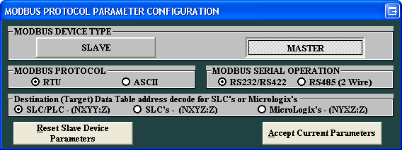
In the configuration software the type of PLC used is selected. See below.
PLC’s and SLC’s - (NXYY:Z)
Use this format if the SLC, PLC, or other device allows up to 999:9999 to be entered for the file:word.
• X – Registers or Coils
• 0 = 0X, 1 = 1X, 3 = 3X, 4 = 4X
• YY – Slave address
• 1 to 99
• Z – Register address
• 1 to 9999
Example: N41:3036 will access register 43036 from Modbus Slave address 1.
SLC’s - (NXYZ:Z)
Use this format if the SLC, PLC, or other device allows up to 999:999 to be entered for the file:word.
• X – Registers or Coils
• 0 = 0X, 1 = 1X, 3 = 3X, 4 = 4X
• Y – Slave address
• 1 to 9
• Z:Z – Register address
• Z before the colon ‘:’ – Thousands digit
• 0 to 9
• Z after the colon ‘:’ – Ones to Hundreds digits
• 0 to 999
Example: N413:36 will access register 43036 from Modbus Slave address 1.
NOTE: Z:Z cannot equal 0:0. The minimum value for Z:Z is 0:1.
MicroLogix’s and SLC’s - (NYXZ:Z)
Use this format if the SLC, PLC, or other device allows up to 255:255 to be entered for the file:word.
• Y – Slave address
• 0 = slave address 1, 1 = slave address 2, 2 = slave address 3
• X – Registers or Coils
• 0 = 0X, 1 = 1X, 3 = 3X, 4 = 4X
• Z:Z – Register address
• Z before the colon ‘:’ – Thousands digit
• 0 to 9
• Z after the colon ‘:’ – Ones to Hundreds digits
• 0 to 255
Example: N43:36 will access register 43036 from Modbus Slave address 1.
NOTES:
1. Z:Z cannot equal 0:0. The minimum value for Z:Z is 0:1.
2. Slave address 3 cannot access registers or coils above 5255.
For more information about using PLC-5 Typed Commands with the decoding formats shown above, refer to section 1.2.4 of this manual.
1.1.1 DESTINATION DATA TABLE ADDRESS FORMAT
If a PLC is being used to generate messages for the DL3500 to convert and send to a Modbus network, values are
entered into the Destination Data Table Address of the PLC’s DH+ Message Command in the format below.
MMI’s and other applications would have a similar destination address structure for reading and writing data to and
from a PLC (refer to your OEM application documentation).
When a PLC is communicating with other devices over the DH+ network, the destination data table address (DDTA) has different meanings depending on whether it is communicating with another PLC or if it is communicating with a DL3500 Modbus Master. Below are descriptions of the different meanings for the DDTA.
The usual format of the destination data table address (DDTA) is: T F : e
T, F, and e are explained below.
Communicating with another PLC on the DH+ network
• T = File Type (O = output, I = input, B = binary, N = integer, etc.)
• F = File Number (0 - 63, 0-255, 0 - 999, or 0 - 9999) *
• e = Word Number (0 - 255, 0 - 999 or 0 – 9999) *
Communicating with a DL3500 Modbus Master on the DH+ network using PLC-3 commands
Data and Control Functions
• T = Modbus Command (B, N, S, F)
• F = Modbus Slave Address (1 - 255)
• e = Modbus Coil/Register (1 - 9999)Diagnostic Functions (Dxyyy:zzzz)
• T = Modbus Command (D)
• F = Sub-function Command / Slave Address (xyyy)
• e = Sub-function Command / Data (zzzz)
For more details about mapping the data and control functions and the diagnostic functions using PLC-3 commands, see section 1.2.3
Communicating with a DL3500 Modbus Master on the DH+ network using PLC-5 commands Data and Control Functions (includes Diagnostic Function)
• T = Not used **
• F = PLC-5 Decoding Format (NXYY:Z, NXYZ:Z, or NYXZ:Z Format)
• e = PLC-5 Decoding Format (NXYY:Z, NXYZ:Z, or NYXZ:Z Format)
For more details about mapping the data and control functions and the diagnostic functions using PLC-5 commands, see sections 1.1 and 1.2.4
* Depends on PLC type.
** To avoid errors when downloading your program to the PLC, a file type is needed so that a legal format for the DDTA is used.
1.2 DH+ AND MODBUS COMMANDS
1.2.1 DH+ MESSAGE COMMANDS
The DL3500-DH+ set to Modbus Master Mode can generate Modbus protocol functions on receipt of the following DH+ message commands:
• PLC-3 Word Range Read or Word Range Write Commands
• PLC-5 Typed Read or Typed Write Commands
• PLC-5 Word Range Read and Writes
A-B PLCs can generate the following commands:
• SLC’s PLC-5 Typed Read/Write Commands
• PLC-3 PLC-3 Word Range Read/Write Commands
• PLC-5 PLC-3 Word Range Read/Write Commands and PLC-5 Typed Read/Write Commands
1.2.2 MODBUS COMMANDS
The Modbus commands and addresses that can be generated depend on the specific DH+ message command
received. The DL3500-DH+ in Master Mode is designed to work with DH+ message commands including PLC-5
Typed Read and Write and PLC-3 Word Range Read and Write. Use the PLC-3 Word Range Read and Write
commands whenever possible because the larger address field of these commands provides the additional flexibility
necessary to generate the full range of Modbus commands and addresses.
1.2.3 PLC-3 WORD RANGE COMMANDS (PLC-3’s and 5’s)
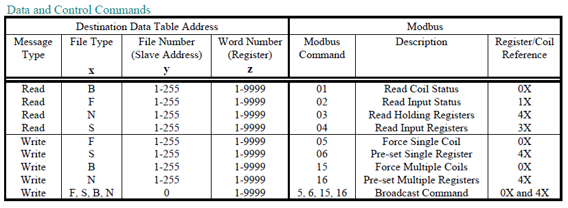
MODBUS DATA AND CONTROL COMMANDS USING PLC-3 WORD RANGE READ / WRITE COMMANDS
On receiving a PLC-3 Word Range Read or Word Range Write Message Command (MC) a DL3500 Modbus Master decodes the command’s Destination Data Table Address (DDTA) File type (character). Then, dependent on whether the DH+ message is a read or a write it can generate the appropriate Modbus command as shown in the table below.
The following DDTA format is used for mapping PLC-3 Word Range Read/Write commands to Modbus commands:
x y : z
Where x = File Type y = File Number z = Word Number
x y : z
Where x = File Type y = File Number z = Word Number
For Modbus command 05, set the first word of data in the PLC data table to FF00 (hex) to turn the coil ON and 0000 to turn the coil OFF.
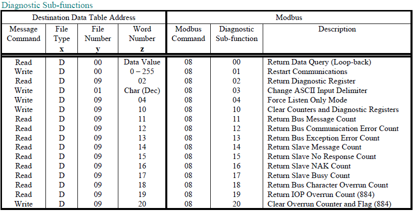
1.2.3.1 MODBUS DIAGNOSTICS COMMANDS
MODBUS DIAGNOSTIC COMMANDS USING PLC-3 WORD RANGE R/W COMMANDS
1.2.4 PLC-5 TYPED R/W & WORD RANGE R/W (PLC-5’s and SLC’s)
MODBUS DATA AND CONTROL COMMANDS USING PLC-5 TYPED READ / WRITE COMMANDS
On receiving a PLC-5 Typed Read or Word Range Write Message Command (MC) a DL3500-DH+ Modbus Master decodes the command’s Destination Data Table Address (DDTA) File type (character). Then, depending on whether the DH+ message is a read or a write command, it can generate the appropriate Modbus command as shown below.
1.2.4.1 PLC5 TYPED COMMANDS USING NXYY:Z DECODE
Use this format if the SLC, PLC, or other device allows up to 999:9999 to be entered for the file:word. This
format allows access to all Modbus registers and coils for slaves 1 to 99.
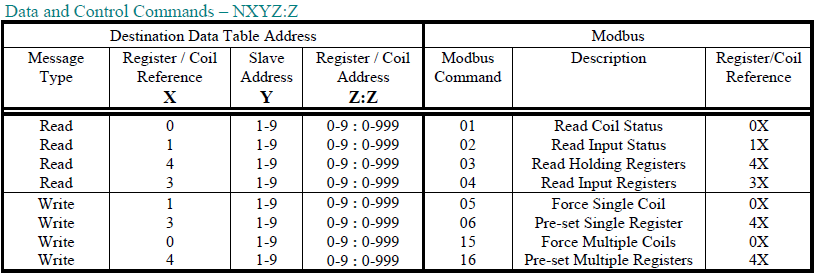
1.2.4.2 PLC5 TYPED COMMANDS USING NXYZ:Z DECODE
Use this format if the SLC, PLC, or other device allows up to 999:999 to be entered for the file:word. This
format allows access to all Modbus registers and coils for slaves 1 to 9.
1. Leading zeros in the Destination Data Table Address can be left out.
2. Register/Coil Address
• Z before the colon ‘:’ – Thousands digit
• Z after the colon ‘:’ – Ones to Hundreds digits
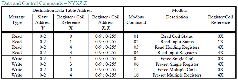
1.2.4.3 PLC5 TYPED COMMANDS USING NYXZ:Z DECODE
Use this format if the SLC, PLC, or other device allows up to 255:255 to be entered for the file:word. This format allows access to certain Modbus registers and coils for slaves 1 to 3.
1. Leading zeros in the Destination Data Table Address can be left out.
2. Register/Coil Address
• Z before the colon ‘:’ – Thousands digit
• Z after the colon ‘:’ – Ones to Hundreds digits
• Register and coil addresses range from 1-255, 1000-1255, 2000-2255, etc.
3. Slave Address
• 0 = slave address 1, 1 = slave address 2, 2 = slave address 3 4. Slave address 3 cannot access registers or coils above 5255.
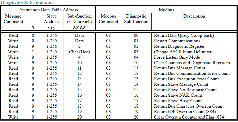
1.2.4.4 MODBUS DIAGNOSTIC COMMANDS
When using PLC-5 Typed Read / Write commands, the Diagnostic commands have the following PLC-3 address format :DXyyy:ZZZZ
1.2.5 BROADCAST COMMAND
A-B’s DH+ network does not typically support Broadcast. However, using a PLC message command with the
Destination Data Table Address containing a File Address of 0 in the write commands specified in sections 1.3.1
and 1.3.2 above will generate a Modbus Broadcast command to all Modbus Slave stations. The DL3500-DH+ will
not get an “ACK” response to a Broadcast command from any Modbus slave device.
Note: This is not supported for section 1.2.4.3 PLC-5 Typed commands using the NYXZ:Z decode option.
1.3 DH+ MESSAGE COMMAND
To read and write to slave devices on Modbus it is necessary to program DH+ message instructions in one (or more)
active PLC’s on the DH+ network. You can use either PLC-3, PLC-5 Word Range Read / Write or PLC-5 Typed
Read / Write communication commands. Below is an example of a message that uses RSLogix to write 10 words of
data starting from N7:0 to Modicon holding registers 40001 to 40010 in slave device 4 using PLC-5 NXYZ:Z
decoding format.
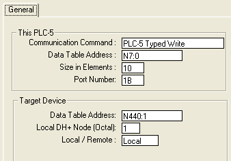
Setup for the DL3500 Modbus Master using the RSLogix message instruction
Entering either a “PLC-5 Typed Read/Write” or “PLC-3 Word Range Read/Write” in the Communication Command determines the kind of decoding scheme will be used and what kind of Modbus command will be executed. For more information on the types of decoding schemes, see section 1.2.3 for PLC-3 commands and section 1.2.4 for PLC-5 commands. If using PLC-3 commands, the DL3500 Modbus Master interprets the “N” of the Destination Data Table Address to be Modbus command 03 if a “PLC-3 Word Range Read” command is issued and Modbus command 16 if a “PLC-3 Word Range Write” command is issued.
Below is a description of the message parameters used to read or write data to slave devices on the Modbus network.
This PLC
Communication Command : Determines whether the command is a “PLC-3 Word Range Read/Write” or a “PLC-5 Typed Read/Write”.
Data Table Address : Starting address of the A-B file and word where data is written or read.
Size in Elements : The number of words from the starting A-B address used in reading or writing data.
Port Number : The DH+ port that is connected to the DL3500 Modbus Master.
Target Device
Data Table Address : The Modbus command, slave station, and registers/coils are entered here in the chosen decoding format.
Local DH+ Node : The node of the DL3500 Modbus Master.
Local / Remote : The network path that the DL3500 Modbus Master is connected through.
Check that the Modbus Slave Station address and Modbus Registers required can be entered into the specific PLC’s Destination Data Table Address field using PLC programming software.
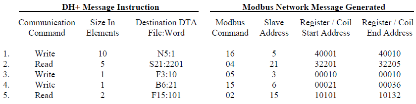
1.3.1 A-B TO MODBUS EXAMPLES
Below are some examples for writing the destination data table address using the formats discussed in this manual.
These examples are to aid the programmer in setting up an Allan-Bradley PLC, SLC, or other device on the DH+
network as a Modbus master. These examples only show the destination data table address and do not show the
source data table address.1.3.1.1 PLC-3 Word Range Commands
Examples
1. Integer - Writing to Modicon registers 40001 to 40010 in slave 5
2. Integer - Reading from Modicon registers 32201 to 32205 in slave 21
3. Binary - Writing to Modicon coil 00010 in slave 3
4. Binary - Writing to Modicon coils 00021 to 00036 in slave 6
5. Binary - Reading from Modicon coils 10101 to 10132 in slave 15
When mapping binary files using Modbus commands 01, 02, and 15, the DL3500 Modbus Master maps 16 consecutive coils for every 1 element. Therefore 2 elements will map 32 consecutive coils.
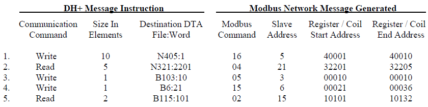
1.3.1.2 PLC-5 Typed Commands (NXYY:Z)
Examples
1. Integer - Writing to Modicon registers 40001 to 40010 in slave 5
2. Integer - Reading from Modicon registers 32201 to 32205 in slave 21
3. Binary - Writing to Modicon coil 00010 in slave 3
4. Binary - Writing to Modicon coils 00021 to 00036 in slave 6
5. Binary - Reading from Modicon coils 10101 to 10132 in slave 15
When mapping binary files using Modbus commands 01, 02, and 15, the DL3500 Modbus Master maps 16 consecutive coils for every 1 element. Therefore 2 elements will map 32 consecutive coils.
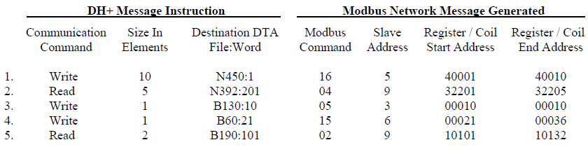
1.3.1.3 PLC-5 Typed Commands (NXYZ:Z)
Examples
1. Integer - Writing to Modicon registers 40001 to 40010 in slave 5
2. Integer - Reading from Modicon registers 32201 to 32205 in slave 21
3. Binary - Writing to Modicon coil 00010 in slave 3
4. Binary - Writing to Modicon coils 00021 to 00036 in slave 6
5. Binary - Reading from Modicon coils 10101 to 10132 in slave 15
Note :
When mapping binary files using Modbus commands 01, 02, and 15, the DL3500 Modbus Master maps 16 consecutive coils for every 1 element. Therefore 2 elements will map 32 consecutive coils.
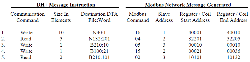
1.3.1.4 PLC-5 Typed Commands (NYXZ:Z)
Examples
1. Integer - Writing to Modicon registers 40001 to 40010 in slave 5
2. Integer - Reading from Modicon registers 32201 to 32205 in slave 21
3. Binary - Writing to Modicon coil 00010 in slave 3
4. Binary - Writing to Modicon coils 00021 to 00036 in slave 6
5. Binary - Reading from Modicon coils 10101 to 10132 in slave 15
Note :
When mapping binary files using Modbus commands 01, 02, and 15, the DL3500 Modbus Master maps 16 consecutive coils for every 1 element. Therefore 2 elements will map 32 consecutive coils.
1.4 COMMUNICATIONS SEQUENCE
The DL3500-DH+ receives message commands from a PLC over its DH+ port, converts them to the appropriate
Modbus message and sends them out on its serial port. The Modbus Slave response is received, translated into an
appropriate DH+ response and then returned to the originating PLC.
Modbus Master/Slave protocol does not permit multiple messages on the Modbus network. The DL3500 processes one message at a time out of its Modbus port, although it can handle multiple requests from PLC’s on the DH+ network, the programmer should ensure a response is received before initiating another request. The DL3500 unit will respond to the DH+ interface with appropriate error messages in the event of detectable errors on Modbus such as timeouts.
Modbus Master/Slave protocol does not permit multiple messages on the Modbus network. The DL3500 processes one message at a time out of its Modbus port, although it can handle multiple requests from PLC’s on the DH+ network, the programmer should ensure a response is received before initiating another request. The DL3500 unit will respond to the DH+ interface with appropriate error messages in the event of detectable errors on Modbus such as timeouts.
1.5 MODBUS MESSAGE DATA LENGTH CONSIDERATIONS
The following shows the maximum number of holding registers that can be sent or received in a single Modbus
message when using the DL3500 gateway. The limits are because of the different structure of Modbus and A-B
DH+ protocols, and also due to the internal memory structure of the DL3500.
• Up to 100 Modbus Holding Registers can be read in a single transaction • Up to 100 Modbus Holding Registers can be written in a single transaction
• Up to 100 Modbus Holding Registers can be read in a single transaction • Up to 100 Modbus Holding Registers can be written in a single transaction
1.6 MODBUS MASTER USING BM85 MODBUS PLUS / MODBUS BRIDGE MUX
The DL3500-DH+ Modbus Master will also communicate with Modicon PLCs and other devices on Modbus Plus
when connected to one of the four Modbus ports of a NW-BM85-000 Modbus Plus/Modbus Network Bridge Mux
(see DL3500 users guide for cable drawings).
If PLCs and other stations on DH+ are required to initiate communications with one or more Modicon PLCs on Modbus Plus then the BM85’s Bridge Mux port connecting it to the DL3500-DH+ must be configured in Slave mode.
The serial communications parameters for the Bridge Mux Modbus port interface to the DL3500-DH+ must be the same as those set in the DL3500.
1.7 DH+ AND MODBUS - GENERAL
Each addressed slave station must be a unique address on Modbus and the DL3500-DH+ must be the only Master
Station on the Modbus network. Any station on the DH+ network can be a “Master” that can address any Modbus
Slave Station from 1 - 255. This means that effectively the Modbus network can have multiple A-B PLC Modbus
Masters with the DL3500 acting as a traffic cop.
Modbus (Slave) station address numbers may be the same as DH+ station address numbers provided that all Slave Station addresses are unique on Modbus, and all DH+ network addresses are unique on the DH+ network.
Modbus (Slave) station address numbers may be the same as DH+ station address numbers provided that all Slave Station addresses are unique on Modbus, and all DH+ network addresses are unique on the DH+ network.
2.0 MODBUS MASTER NETWORK APPLICATIONS
2.1 MASTER TO MODBUS SLAVE NETWORK
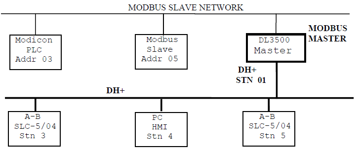
NOTE:
PLC5s, SLC5/04s and HMIs on the A-B DH+ network can be programmed to communicate with any Slave device on the Modbus Slave network. Modbus and DH+ addresses can be the same.
PLC5s, SLC5/04s and HMIs on the A-B DH+ network can be programmed to communicate with any Slave device on the Modbus Slave network. Modbus and DH+ addresses can be the same.
2.2 MASTER TO MODBUS PLUS VIA BM85 MODBUS BRIDGE
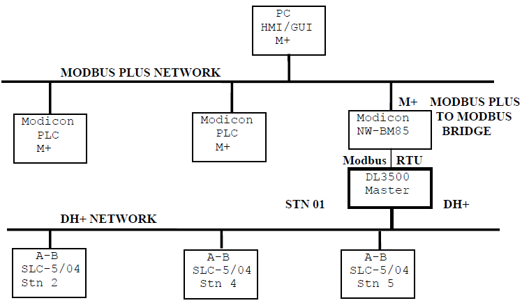
NOTE:
PLC5s, SLC5/04s and HMIs on the DH+ network can be programmed to communicate with any station on the Modbus Plus network
PLC5s, SLC5/04s and HMIs on the DH+ network can be programmed to communicate with any station on the Modbus Plus network