Wonderware Application Note
Configuring the ABKF2 I/O Server With Equustek’s DL products.
PDF Download
About this application Note
This application note describes how to use the Wonderware FactorySuite 2000 ABKF2 I/O Server to communicate with a PLC3s, PLC5s, SLC500s and MicroLogix’s through a direct serial connection (DL3500 or DL4500). The server is listed as the Allen-Bradley serial server in the Wonderware FactorySuite 2000 install program.
This technical note assumes :
• You have installed the Wonderware FactorySuite 2000 ABKF2 I/O Server.
• You have Equustek’s products as DL3500, DL4500 or others.
• You have a reasonable knowledge of the SLC and programming software you are using.
• You have Equustek’s products as DL3500, DL4500 or others.
• You have a reasonable knowledge of the SLC and programming software you are using.
The application note is designed to aid the user in configuration of the driver software element (ABKF2) of Wonderware’s InTouch MMI software package. This driver program is a separate element of InTouch, and allows identification of the various addresses and protocols that the MMI program takes to monitor/control various hardware components on the network, as designed in the main InTouch window.
Setup Procedure
Configuring the ABKF2 DDE Server
Before you use the DDE server, you must configure it with the following information:
• The PC serial port, and the protocol, baud rate and communication parameters.
• The PLC processor type, the connection type, and how often the server should read data from the PLC.
• The PLC processor type, the connection type, and how often the server should read data from the PLC.
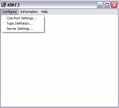
Start the ABKF2 DDE server (abkf2.exe) and maximize the application window.
The first screen that appears allows three options under the "Configure" menu :
Configure the DDE server by selecting items from the Configure menu.
COM Port Settings
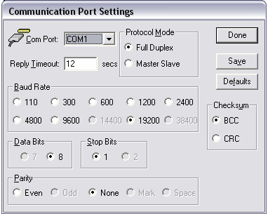
Choose Configure/Com Port Settings…. Select the COM Port (COM1, COM2, etc) you are using and complete the following steps to configure the communication parameters :
1. Leave Reply Timeout at its default value.
2. In the Protocol Mode group box, select Full Duplex.
3. Set the Baud Rate, Data Bits, Stop Bits, Parity and Checksum to match those configured in the PLC.
4. Click on Save to save the settings, and then click on Done.
2. In the Protocol Mode group box, select Full Duplex.
3. Set the Baud Rate, Data Bits, Stop Bits, Parity and Checksum to match those configured in the PLC.
4. Click on Save to save the settings, and then click on Done.
Note: These settings configure communication between the computer and your unit (DL3500, DL4500). (Either via a serial cable and an existing Com Port, or the USB cable and its corresponding Virtual Com Port). All settings must be consistent with those chosen when configuring the DL3500 with the DL32 configuration program. The latest version of DL32 is available at http://www.equustek.com/downloads.html
Topic definition
You must create at least one topic for each SLC or PLC with which you are communicating. The topic
contains information such as the serial port you are using to communicate with the SLC or PLC and how
often the topic is updated.
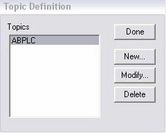
Choose Configure/Topic Definition... . Click on New to create a new topic to be assigned. This name
must be referred back to in the InTouch window, or select an existing topic from the Topics list box and
click on Modify to display the ABKF2 Topic Definition dialog box.
Each communication route between the various elements must be identified separately, and are given
distinct names.
In the ABKF2 Topic Definition dialog box:
1. If you are creating a new topic, enter a unique topic name in the Topic name field.
2. Select the COM Port you are using to communicate with the SLC or PLC.
3. In the PLC Family group box, choose PLC-5.
4. In the Connect Type list box, choose KF2 DH+.
5. In the Polling group box, leave the Discrete Read Block Size and the Register Read Block Size at their
default values and set the Update Interval to an appropriate value.
The update interval is how often the DDE server reads values from the PLC for this topic.
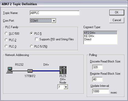 6. Click OK, and Done.
Test the I/O Servers with the WWClient Utility
Click the Start button, all programs/Wonderware FactorySuite/Common and select WWClient
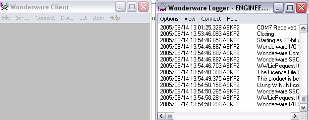
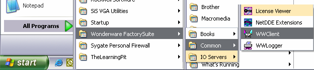 These windows should appear: (Note that the Wonderware Logger will also automatically start.
Minimize the WWLogger window for now so that you can clearly see the Wonderware Client window.)
These windows should appear: (Note that the Wonderware Logger will also automatically start.
Minimize the WWLogger window for now so that you can clearly see the Wonderware Client window.)
Choose “Connect” on the Wonderware Client window. This page should appear.
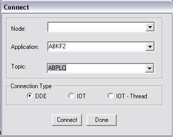 1. Type in the name of the I/O Server in the Application listbox (example, “ABKF2” for the
ABKF2 I/O Server) and the Topic name in the Topic listbox (example, “ABPLC”).
1. Type in the name of the I/O Server in the Application listbox (example, “ABKF2” for the
ABKF2 I/O Server) and the Topic name in the Topic listbox (example, “ABPLC”).
Select either the DDE or IOT radio button. (If your Wonderware I/O Server is release 7.0 or
greater, then it can communicate using SuiteLink. You can verify the I/O Server release by
selecting Help/About from the I/O Server menu.)
Then click the Connect button. You should see an established DDE conversation to the I/O
Server appear in the Wonderware Client window as shown in the example below.
If the DDE conversation does not appear, then the connection to the I/O Server failed. (This is the same
as InTouch issuing the error “Could not Initiate DDE Conversation.”) Check the following:
1. Verify that the I/O Server is properly configured and running.
2. Verify that the I/O Server’s name is spelled correctly in the Application listbox on the Connect
dialog box.
3. Verify that the Topic name was created in the I/O Server. Also, verify that the Topic name is
spelled correctly in the Topic listbox on the Connect dialog box.
4. Verify that the I/O Server can support the selected Connection Type on the Connect dialog box.
(Remember that only version 7.0 and later of a Wonderware I/O Server can use the IOT
connection type.)
5. Click the Done button once you have verified the DDE conversation was successful to the I/O
Server.
Select either the DDE or IOT radio button. (If your Wonderware I/O Server is release 7.0 or greater, then it can communicate using SuiteLink. You can verify the I/O Server release by selecting Help/About from the I/O Server menu.)
Then click the Connect button. You should see an established DDE conversation to the I/O Server appear in the Wonderware Client window as shown in the example below.
2. Verify that the I/O Server’s name is spelled correctly in the Application listbox on the Connect dialog box.
3. Verify that the Topic name was created in the I/O Server. Also, verify that the Topic name is spelled correctly in the Topic listbox on the Connect dialog box.
4. Verify that the I/O Server can support the selected Connection Type on the Connect dialog box. (Remember that only version 7.0 and later of a Wonderware I/O Server can use the IOT connection type.)
5. Click the Done button once you have verified the DDE conversation was successful to the I/O Server.
Testing the I/O Server With the Register and Advise Commands
1. Select Item from the WWClient menu. The Item dialog box will appear:
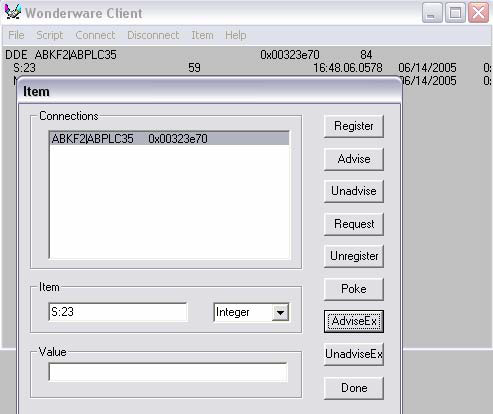 1. Type in a valid Item name that you want to read a value from in the Item listbox. (Example,
“S:23”, which is the real time in seconds for an Allen-Bradley PLC 5 processor or “S:4” which is
the real time in seconds for an Allen-Bradley SLC processor.)
Select the type of the Item from the dropdown list (that is, Integer, Real, Discrete, or String).
1. Type in a valid Item name that you want to read a value from in the Item listbox. (Example,
“S:23”, which is the real time in seconds for an Allen-Bradley PLC 5 processor or “S:4” which is
the real time in seconds for an Allen-Bradley SLC processor.)
Select the type of the Item from the dropdown list (that is, Integer, Real, Discrete, or String).
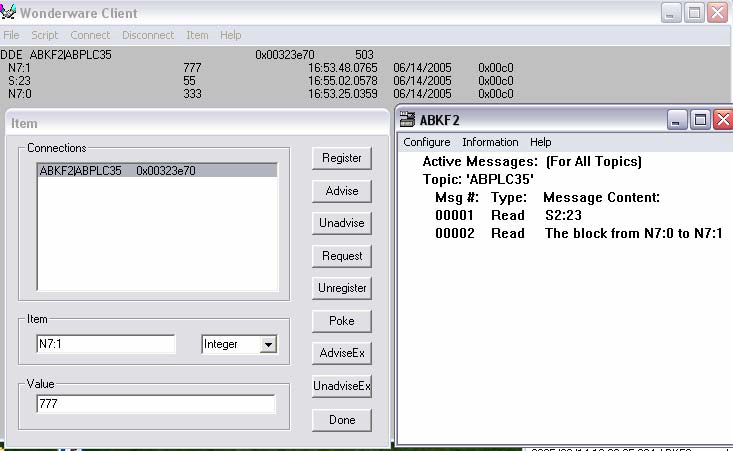
2. Click both the Register and Advise button respectively or the AdviseEx button.
You should see the Item appear and then its value to the right in the Wonderware Client window,
as shown in the example below. The example below shows that the Item is being updated every
second. This confirms that the I/O Server is configured properly.
You will see an error stating that the Advise operation failed if it was unable to display the Item
and its value. You should also check the WWLogger window for any related error messages. If
you receive an error from WWClient, check the I/O Server configuration, the PLC hardware and
its software settings, cabling, and other related items.
2. Click both the Register and Advise button respectively or the AdviseEx button. You should see the Item appear and then its value to the right in the Wonderware Client window, as shown in the example below. The example below shows that the Item is being updated every second. This confirms that the I/O Server is configured properly.
You will see an error stating that the Advise operation failed if it was unable to display the Item and its value. You should also check the WWLogger window for any related error messages. If you receive an error from WWClient, check the I/O Server configuration, the PLC hardware and its software settings, cabling, and other related items.
Testing the I/O Server With the Poke Command
Do these steps to see if WWClient can successfully Poke (that is, write) a value to an Item in the PLC.
1. Select Item from the WWClient menu. The Item dialog box will appear:
2. Type in the Item name for a valid and configured PLC in the Item listbox to which values can be
written. Then select the Item name’s type from the dropdown list (that is, Integer, Discrete, Real,
or String). In our example, we entered the Allen-Bradley File N7 as the Item name and Integer as
the type.
Type in a valid number for the Item name in the Value listbox (example, 777).
Click the Poke button. You should see the value of 777 written and displayed in the Allen-
Bradley N7 File as shown above.
3. Confirm that the Poke command was successful by executing the PLC’s programming software
and viewing the data table(s) in the PLC.
For example, here are the results of the Topic that was connected, ABPLC:
 To remove the DDE conversation by Item name, do these steps:
1. Select Item from the WWClient menu and highlight the desired Topic name from the
Connections list.
2. Type in the Item name in the Item listbox from which you wish to remove the DDE
conversation.
Click either the Unregister or UnadviseEX button. The Item name will be removed and no
longer appear in the Wonderware Client window.
To remove the DDE conversation by Topic name, do these steps:
1. Select Disconnect from the WWClient menu. The Disconnect dialog box will appear.
2. Highlight the desired Topic name from the Connection List from which you wish to remove the
DDE conversation.
Click the Disconnect button. The Topic name will be removed and no longer appear in the
Disconnect dialog box and in the WWClient screen.
The appropriate choice depends on the mode of the DL3500 unit, and the network architecture. See the following two cases on setting the NODE number.
Case 1 - Typical Installation :
 In a typical installation, a PLC is being accessed; therefore
the address entered under “node” is that of the PLC. The
InTouch program's tag describes the location within the
PLC data table where the device information is stored.
In a typical installation, a PLC is being accessed; therefore
the address entered under “node” is that of the PLC. The
InTouch program's tag describes the location within the
PLC data table where the device information is stored.
The InTouch program's tag describes the location within
the PLC data table where the device information is stored.
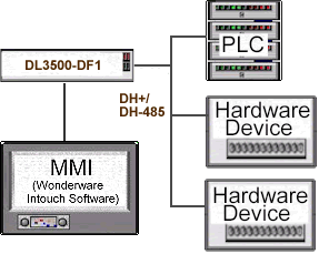
Case 2 – Accessing a Modbus Slave Device :
To monitor/control a Modbus
unit from the MMI, a converter
must be present in the network
to convert from DH+ to
Modbus. There are two ways
that the MMI may be set up to
perform monitoring and control
of the Modbus device(s):
a) The MMI's DL3500-DF1 unit may send and receive messages directly to and from the DL3500-
Modbus Master (without going through the PLC to access the Modbus device(s). In this case, The
address entered is that of the DL3500-Modbus. The tag entered in the InTouch program must
provide the Modbus slave address (in dec) and the Modbus register location.
See DL3500-Modbus Master Application note for decoding
b) The MMI's may also access Modbus device information through the PLC. In this case, the address
entered is that of the PLC, and the InTouch program's tag describes the location within the PLC data
table where the Modbus device information is stored. When programming the PLC, it is crucial that
the MSG instruction be programmed to access the local node address of the DL3500-Modbus device
on the DH+ or DH-485 network, and the destination table address describe the Modbus address
mapping.
See DL3500-Modbus Master Application note for decoding
See DL3500-Modbus Master Application note for decoding
See DL3500-Modbus Master Application note for decoding