Modbus
Application Note
PDF Download
Using ControlLogix With Equustek’s DL products.
About this Application Note
This application note describes how to configure and use our Modbus device (Equustek’s DL products) with the ControlLogix on the DH+ network.
The information contained in this application note is supplementary information specific to Modbus not contained in the regular User's Guide.
Master or Slave mode?
This application note is divided into two parts, Modbus Master and Modbus Slave modes; they correspond to the mode the DL product is going to be on the Modbus Network, and which side either DH+ or Modbus the commands will be initiated on.
Master mode is used when a device on the DH+ network is going to initiate all communications with one or many Modbus slave devices. Please Refer to DL3500-DH+/Modbus Master Application note.
Slave mode is used when a device on the Modbus network is going to initiate all communications with one or many SLC’s, PLC’s or other DH+ devices. Please Refer to DL3500-DH+/Modbus Slave Application note.
The application notes generally assume that a ControlLogix or other DH+ device which can originate commands to Modbus via a DL product in master mode, or responding to Modbus commands via a DL product in slave mode. Only devices capable of transmitting DH+ message commands in PLC5 (or PLC3) format and able to receive DH+ message commands in PLC5 format can be used with the DL products on the DH+ network, including SLC’s, MicroLogix’s, ControlLogix’s and HMIs as well as other intelligent devices.
Due to differences between DH+ and Modbus protocols and the universal design of the DL product there are differences between the lengths of messages, error handling and addressing which have to be carefully considered by the Systems Designer, Programmer and Installer.
CAUTION:
Incorrect configuration may result in unsafe operation, damage to equipment or safety hazard to personnel. Read the DL3500 User's Guide and the appropriate application notes carefully before putting your equustek’s product on-line. The hardware and software must be fully tested off-line in a safe “TEST” environment prior to putting the unit on-line in an operational environment.
The Modbus Master Application notes contain configuration information for the DL3500-DH+ protocol and should be used in conjunction with the DL3500 User's Guide.
The Modbus Master Application notes contain configuration information for the DL3500-DH+ protocol and should be used in conjunction with the DL3500 User's Guide.
NOTES:
1. The unit that you have received can be configured as Modbus Master or Modbus Slave. Ensure that you understand and carefully follow the specific configuration procedures for the Modbus protocol.
2. There are significant differences between the configuration, programming and operational requirements of the Modbus Master and Modbus Slave protocols.
3. If you configure the DL3500 for Modbus Master Operation it must be the only master on the Modbus network. A station on DH+ originates commands to the DL3500-DH+ Modbus Master that then re-transmits them over Modbus to a Modbus Slave device. Other intelligent DH+ devices capable of initiating DH+ messages in PLC5 (or PLC3) format and able to receive PLC5 message commands could also be used as the DH+ “master”.
4. Be sure to fully test the hardware and software off-line to ensure that you understand its configuration and operation. Prior to putting the DL3500 on-line in an production process, the operation of the complete system should be fully tested on-line in a safe "test" environment.
5. Due to differences between DH+ and Modbus hardware and software, there are differences between the lengths of messages, error handling and addressing which have to be carefully considered by the Systems Designer, Programmer and Installer.
6. Additional literature regarding DH+, Modbus and PLC products can be obtained from Modicon and A-B. Suggested reference materials for A-B DH+ protocol is shown in section 1.7 of the User's Guide.
TECHNICAL SUPPORT
This application note describes how to configure and use our Modbus device (Equustek’s DL products) with the ControlLogix on the DH+ network.
The information contained in this application note is supplementary information specific to Modbus not contained in the regular User's Guide.
Master or Slave mode?
This application note is divided into two parts, Modbus Master and Modbus Slave modes; they correspond to the mode the DL product is going to be on the Modbus Network, and which side either DH+ or Modbus the commands will be initiated on.
Master mode is used when a device on the DH+ network is going to initiate all communications with one or many Modbus slave devices. Please Refer to DL3500-DH+/Modbus Master Application note.
Slave mode is used when a device on the Modbus network is going to initiate all communications with one or many SLC’s, PLC’s or other DH+ devices. Please Refer to DL3500-DH+/Modbus Slave Application note.
The application notes generally assume that a ControlLogix or other DH+ device which can originate commands to Modbus via a DL product in master mode, or responding to Modbus commands via a DL product in slave mode. Only devices capable of transmitting DH+ message commands in PLC5 (or PLC3) format and able to receive DH+ message commands in PLC5 format can be used with the DL products on the DH+ network, including SLC’s, MicroLogix’s, ControlLogix’s and HMIs as well as other intelligent devices.
Due to differences between DH+ and Modbus protocols and the universal design of the DL product there are differences between the lengths of messages, error handling and addressing which have to be carefully considered by the Systems Designer, Programmer and Installer.
CAUTION:
Incorrect configuration may result in unsafe operation, damage to equipment or safety hazard to personnel. Read the DL3500 User's Guide and the appropriate application notes carefully before putting your equustek’s product on-line. The hardware and software must be fully tested off-line in a safe “TEST” environment prior to putting the unit on-line in an operational environment.
DL3500-DH+ MODBUS MASTER TO A-B DH+ CONFIGURATION
Use this option when the DL3500 is required to be the master on a Modbus network.The Modbus Master Application notes contain configuration information for the DL3500-DH+ protocol and should be used in conjunction with the DL3500 User's Guide.
DL3500-DH+ MODBUS SLAVE TO A-B DH+ CONFIGURATION
Use this protocol when the DL3500 is required to be a slave device on a Modbus network.The Modbus Master Application notes contain configuration information for the DL3500-DH+ protocol and should be used in conjunction with the DL3500 User's Guide.
NOTES:
1. The unit that you have received can be configured as Modbus Master or Modbus Slave. Ensure that you understand and carefully follow the specific configuration procedures for the Modbus protocol.
2. There are significant differences between the configuration, programming and operational requirements of the Modbus Master and Modbus Slave protocols.
3. If you configure the DL3500 for Modbus Master Operation it must be the only master on the Modbus network. A station on DH+ originates commands to the DL3500-DH+ Modbus Master that then re-transmits them over Modbus to a Modbus Slave device. Other intelligent DH+ devices capable of initiating DH+ messages in PLC5 (or PLC3) format and able to receive PLC5 message commands could also be used as the DH+ “master”.
4. Be sure to fully test the hardware and software off-line to ensure that you understand its configuration and operation. Prior to putting the DL3500 on-line in an production process, the operation of the complete system should be fully tested on-line in a safe "test" environment.
5. Due to differences between DH+ and Modbus hardware and software, there are differences between the lengths of messages, error handling and addressing which have to be carefully considered by the Systems Designer, Programmer and Installer.
6. Additional literature regarding DH+, Modbus and PLC products can be obtained from Modicon and A-B. Suggested reference materials for A-B DH+ protocol is shown in section 1.7 of the User's Guide.
Contact Technical Support if you need further information or assistance.
TECHNICAL SUPPORT
Tel : (604) 266-8547
Or E-Mail : info@equustek.com
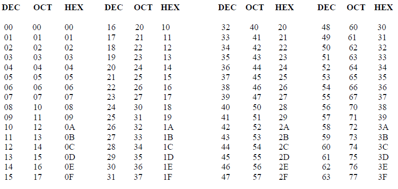
The following table provides a reference between the different radixes used for your reference
DECIMAL TO OCTAL TO HEXADECIMAL ADDRESS CONVERSION TABLE
This technical note assumes :
→ You have installed the RSLogix 5000 on your computer.
→ You have Equustek’s products as DL3500, DL4500 or others.
→ You have a reasonable knowledge of the ControlLogix and programming software you are using.
→ You have a reasonable knowledge about Modbus protocol.
→ You have Equustek’s products as DL3500, DL4500 or others.
→ You have a reasonable knowledge of the ControlLogix and programming software you are using.
→ You have a reasonable knowledge about Modbus protocol.
1.0 DH+/MODBUS MASTER PROTOCOL USING CONTROLLOGIX
The design of the DL3500, DL4500 or other DL device Modbus Master and the PLC message command structure
allows the DL products to use the contents of the Destination Data Table Address in the ControlLogix for direct
address mapping to Modbus. The Equustek’s product decodes the Destination DT Address to access to various
Modbus Slave stations, commands and addresses. The actual Modbus station number and addresses ranges that can
be accessed depends on the PLC type, DF1 message type and Programming software used.
 Modbus Parameters-DL32 V3.10 (Feb’ 05)
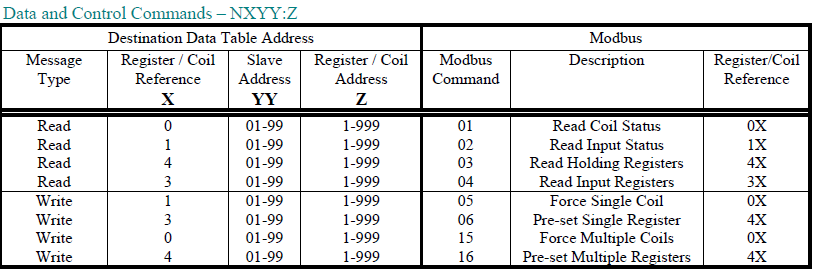
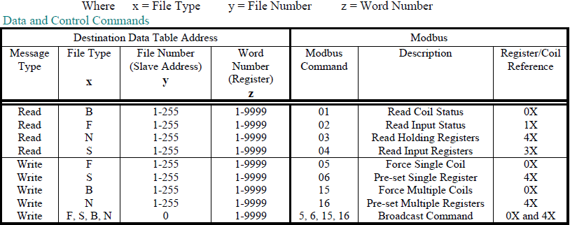
MODBUS DATA AND CONTROL COMMANDS USING PLC-5 TYPED READ / WRITE COMMANDS
On receiving a PLC-5 Typed Read or Word Range Write Message Command (MC) a DL3500 (or other DL product) Modbus Master decodes the command’s Destination Data Table Address (DDTA) File type (character). Then, depending on whether the message of the PLC is a read or a write command, it can generate the appropriate Modbus command as shown below.
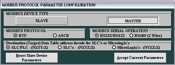
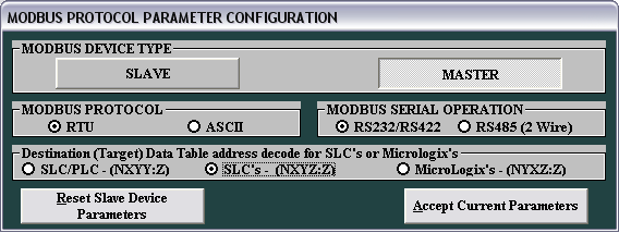
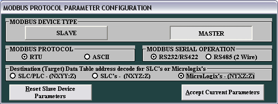
In the configuration software the type of PLC used is selected. See below.
Modbus Parameters-DL32 V3.10 (Feb’ 05)
MODBUS DATA AND CONTROL COMMANDS USING PLC-5 TYPED READ / WRITE COMMANDS
On receiving a PLC-5 Typed Read or Word Range Write Message Command (MC) a DL3500 (or other DL product) Modbus Master decodes the command’s Destination Data Table Address (DDTA) File type (character). Then, depending on whether the message of the PLC is a read or a write command, it can generate the appropriate Modbus command as shown below.
1.1 PLC5 TYPED COMMANDS USING NXYY:Z DECODE
Use this format if the SLC, PLC, or other device allows up to 999:999 to be entered for the file:word. This
format allows access to all Modbus registers and coils for slaves 1 to 99.
In the configuration software the type of PLC used is selected. See below.
Note : Leading zeros in the Destination Data Table Address can be left out.
 Use this format if the ControlLogix, SLC, PLC, or other device allows up to 999:999 to be entered for the file
and word. For this particular format, your starting register address should be less than 1000 (1 to 999).
The file goes up to 999 and the word up to 999.
Use this format if the ControlLogix, SLC, PLC, or other device allows up to 999:999 to be entered for the file
and word. For this particular format, your starting register address should be less than 1000 (1 to 999).
The file goes up to 999 and the word up to 999.
• X – Registers or Coils
• 0 = 0X, 1 = 1X, 3 = 3X, 4 = 4X
• YY – Slave address
• 1 to 99
• Z – Register address
• 1 to 999
Example 1: N401:950 will access register 40950 from Modbus Slave address 1. N401:950
• X = 4 (4X references), YY = 01 (Slave address), Z = 950 (Register address)
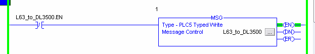
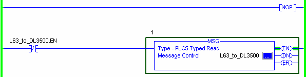
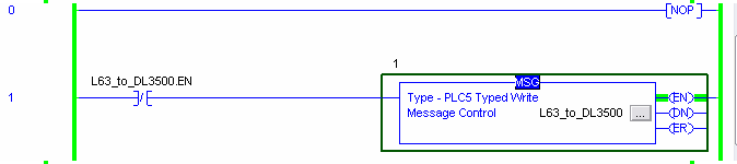
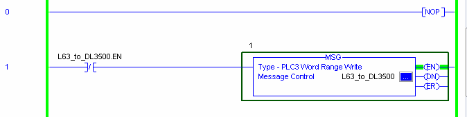
To read and write to slave devices on Modbus it is necessary to program the DF1 message instruction. This is an example of message command you may write using your ControlLogix with the format NXYY:Z
Your starting register address for this example is 950. Your size in element is 15.
This rung uses PLC5 Typed Write command on DH+ network.
SYSTEM CONFIGURATION - Local ControlLogix chassis consists of a 1756-L63 in slot 0 and a 1756-DHRIO in slot 2. Channel A (node 4) of the DHRIO module is connected to a DH+ network. A DL3500 (node 15) is also on the network.
ROUTING TABLE - A routing table is necessary in this example because the 1756-DHRIO module will be used in the Message Communication path to the DL3500. To set up the routing table, the RSLinx software is needed. Set up the necessary link numbers for the backplane of the ControlLogix chassis as well as Channel A of the DHRIO module. For this example: configure the chassis backplane to be "link 0" and Channel A to be "link 0" (0=default).
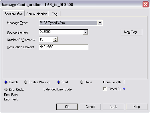
THE MESSAGE INSTRUCTION - Under the 'Configuration Tab' in the Message setup screen, the 'Message Type' is "PLC5 Typed Write", the 'Source Element' is a tag called "DL3500" (your tag in the ControlLogix), the 'Number of Elements' is "15", and the 'Destination Tag' is "N401:950". The 'Source Element' is a Controller scoped tag of data type integer.
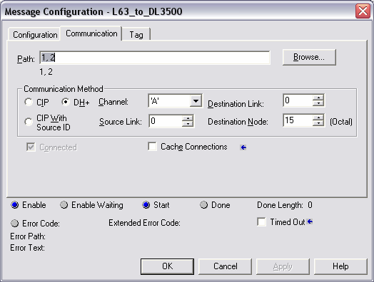
 Under the 'Communication Tab' in the Message setup screen, the communication 'Path' to the DL3500 is specified.
First, the location of the 1756-DHRIO module is specified by the way of the path "1,2" which stands for connection
to the back plane (the number 1) and the connection to slot 2 where the DHRIO module is. Select "DH+" as the
'Communication Method' and use the link numbers configured in the DHRIO module routing table to make the
connection to the DL3500. For this example, 'Channel' is "A", 'Source Link' is the backplane (link "0"), 'Destination
Link' is the DH+ network on Channel A (link "0"), and 'Destination Node' is the DL3500 (node "15").
Under the 'Communication Tab' in the Message setup screen, the communication 'Path' to the DL3500 is specified.
First, the location of the 1756-DHRIO module is specified by the way of the path "1,2" which stands for connection
to the back plane (the number 1) and the connection to slot 2 where the DHRIO module is. Select "DH+" as the
'Communication Method' and use the link numbers configured in the DHRIO module routing table to make the
connection to the DL3500. For this example, 'Channel' is "A", 'Source Link' is the backplane (link "0"), 'Destination
Link' is the DH+ network on Channel A (link "0"), and 'Destination Node' is the DL3500 (node "15").
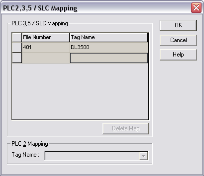
 Now you should map tags, use the Logic > Map PLC/SLC Messages… command from the menu. The dialog has 2
frames; the upper frame is for PLC 3,5/SLC Mapping. Mapping is simple – put in a file number, then select a tag to
map to that file number.
Now you should map tags, use the Logic > Map PLC/SLC Messages… command from the menu. The dialog has 2
frames; the upper frame is for PLC 3,5/SLC Mapping. Mapping is simple – put in a file number, then select a tag to
map to that file number.
Restrictions:
The tag must be in controller scope.
The tag can not be of types AXIS, Motion_Group, Message or User Defined DataType.
For this example, you have DL3500 is mapped to 401.
Example 2: N303:250 will access register 250 from Modbus Slave address 3 N303:250
⇒ X = 3 (3X references), YY = 03 (Slave address), Z = 250 (Register address)
For this example, we still have the format NXYY:Z. Your starting register address for this example is 250. Your size in element is 15.
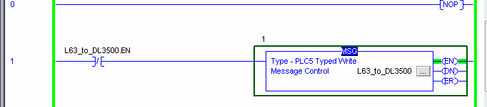
This rung uses PLC5 Typed Read command on DH+ network.
To configure everything follow the same step as example 1 below, make sure to map the register 303 to DL3500.
Example 3 : B003:7 will access register 00007 from Modbus Slave address 3 B003:7
⇒ X = 0 (0X references), YY = 03 (Slave address), Z = 7 (Register address)
For this example, we still have the format BXYY:Z. Your starting register address for this example is 7.
To configure everything follow the same step as example 1 below, make sure to map the register 003 to DL3500. Your starting register address should be less than 1000 (1 to 999).
ControlLogix, SLC’s or PLC’s- (NXYY:Z)
• X – Registers or Coils
• 0 = 0X, 1 = 1X, 3 = 3X, 4 = 4X
• YY – Slave address
• 1 to 99
• Z – Register address
• 1 to 999
Example 1: N401:950 will access register 40950 from Modbus Slave address 1. N401:950
• X = 4 (4X references), YY = 01 (Slave address), Z = 950 (Register address)
To read and write to slave devices on Modbus it is necessary to program the DF1 message instruction. This is an example of message command you may write using your ControlLogix with the format NXYY:Z
Your starting register address for this example is 950. Your size in element is 15.
This rung uses PLC5 Typed Write command on DH+ network.
SYSTEM CONFIGURATION - Local ControlLogix chassis consists of a 1756-L63 in slot 0 and a 1756-DHRIO in slot 2. Channel A (node 4) of the DHRIO module is connected to a DH+ network. A DL3500 (node 15) is also on the network.
ROUTING TABLE - A routing table is necessary in this example because the 1756-DHRIO module will be used in the Message Communication path to the DL3500. To set up the routing table, the RSLinx software is needed. Set up the necessary link numbers for the backplane of the ControlLogix chassis as well as Channel A of the DHRIO module. For this example: configure the chassis backplane to be "link 0" and Channel A to be "link 0" (0=default).
THE MESSAGE INSTRUCTION - Under the 'Configuration Tab' in the Message setup screen, the 'Message Type' is "PLC5 Typed Write", the 'Source Element' is a tag called "DL3500" (your tag in the ControlLogix), the 'Number of Elements' is "15", and the 'Destination Tag' is "N401:950". The 'Source Element' is a Controller scoped tag of data type integer.
Restrictions:
The tag must be in controller scope.
The tag can not be of types AXIS, Motion_Group, Message or User Defined DataType.
For this example, you have DL3500 is mapped to 401.
Example 2: N303:250 will access register 250 from Modbus Slave address 3 N303:250
⇒ X = 3 (3X references), YY = 03 (Slave address), Z = 250 (Register address)
For this example, we still have the format NXYY:Z. Your starting register address for this example is 250. Your size in element is 15.
This rung uses PLC5 Typed Read command on DH+ network.
To configure everything follow the same step as example 1 below, make sure to map the register 303 to DL3500.
Example 3 : B003:7 will access register 00007 from Modbus Slave address 3 B003:7
⇒ X = 0 (0X references), YY = 03 (Slave address), Z = 7 (Register address)
For this example, we still have the format BXYY:Z. Your starting register address for this example is 7.
To configure everything follow the same step as example 1 below, make sure to map the register 003 to DL3500. Your starting register address should be less than 1000 (1 to 999).
1.2 PLC5 TYPED COMMANDS USING NXYZ:Z DECODE
Use this format if the SLC, PLC, or other device allows up to 999:999 to be entered for the file:word. This format allows access to all Modbus registers and coils for slaves 1 to 9.

Notes: 1. Leading zeros in the Destination Data Table Address can be left out.
2. Register/Coil Address
⇒ Z before the colon ‘:’ – Thousands digit
⇒ Z after the colon ‘:’ – Ones to Hundreds digits
2. Register/Coil Address
⇒ Z before the colon ‘:’ – Thousands digit
⇒ Z after the colon ‘:’ – Ones to Hundreds digits
ControlLogix, SLC’s OR PLC’s - (NXYZ:Z)
Use this format if the ControlLogix or other devices allows up to 999:999 to be entered for the file and word.The file goes up to 999 and the word up to 999. For this format, your register address should be between (1 to 9999).
• X – Registers or Coils
⇒ 0 = 0X, 1 = 1X, 3 = 3X, 4 = 4X
• Y – Slave address
⇒ 1 to 9
• Z:Z – Register address
⇒ Z before the colon ‘:’ – Thousands digit
⇒ 0 to 9
⇒ Z after the colon ‘:’ – Ones to Hundreds digits
⇒ 0 to 999
Example 1: N413:36 will access register 43036 from Modbus Slave address 1. N413:36
⇒ X = 4 (4X references), Y = 1 (Slave address), Z:Z = 3:36 (Register address)
NOTE: Z:Z cannot equal 0:0. The minimum value for Z:Z is 0:1.
This is an example of message command you may write using your ControlLogix with the format NXYZ:Z
Your starting register address for this example is 3036. Your size in element is 15.
To configure everything follow the same step as example 1 (Format NXYY:Z) below, make sure to map the register
413 to DL3500. The maximum of slave address you can have here is 9.
Example 2: B098:36 will access register 08036 from Modbus Slave address 9. B098:36
⇒ X = 0 (0X references), Y = 9 (Slave address), Z:Z = 8:36 (Register address)
This is an example of message command you may write using your ControlLogix with the format NXYZ:Z
Your starting register address for this example is 8036. You should make sure to map the register 098 to DL3500.
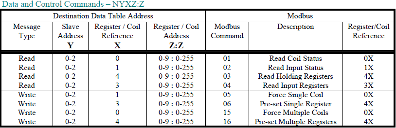
1.3 PLC5 TYPED COMMANDS USING NYXZ:Z DECODE
Use this format if the ControlLogix or other device allows up to 255:255 to be entered for the file:word. This
format allows access to certain Modbus registers and coils for slaves 1 to 3.
Notes : 1. Leading zeros in the Destination Data Table Address can be left out.
2. Register/Coil Address
⇒ Z before the colon ‘:’ – Thousands digit
⇒ Z after the colon ‘:’ – Ones to Hundreds digits
⇒ Register and coil addresses range from 1-255, 1000-1255, 2000-2255, etc.
3. Slave Address
⇒ 0 = slave address 1, 1 = slave address 2, 2 = slave address 3
4. Slave address 3 cannot access registers or coils above 5255.
Use this format if the SLC, PLC, or other device allows up to 255:255 to be entered for the file:word.
• Y – Slave address
⇒ 0 = slave address 1, 1 = slave address 2, 2 = slave address 3
• X – Registers or Coils
⇒ 0 = 0X, 1 = 1X, 3 = 3X, 4 = 4X
• Z:Z – Register address
⇒ Z before the colon ‘:’ – Thousands digit
⇒ 0 to 9
⇒ Z after the colon ‘:’ – Ones to Hundreds digits
⇒ 0 to 255
NOTES :
1. Z:Z cannot equal 0:0. The minimum value for Z:Z is 0:1.
2. Slave address 3 cannot access registers or coils above 5255.
Example 1 : N43:36 will access register 43036 from Modbus Slave address 1.
N043:36⇒ Y = 0 (Slave address 1), X = 4 (4X references), Z:Z = 3:36 (Register address)
NOTE : Z:Z cannot equal 0:0. The minimum value for Z:Z is 0:1.
This is an example of message command (PLC5 Typed Write) you may write using your ControlLogix with the format NYXZ:Z. Your starting register address for this example is 3036. Your size in element is 15.
You should make sure to map the register 043 to DL3500.
Example 2 : N203:36 will access register 03036 from Modbus Slave address 3.
N203:36 ⇒ Y = 2 (Slave address 3), X = 0 (0X references), Z:Z = 3:36 (Register address)
This is an example of message command you may write using your SLC5/04 with the format NYXZ:Z
Your starting register address for this example is 3036. Your size in element is 15.
You should make sure to map the register 203 to DL3500.
Example 3 : N243:36 will access register 43036 from Modbus Slave address 3.
N243:36 ⇒ Y = 2 (Slave address 3), X = 4 (4X references), Z:Z = 3:36 (Register address)
This is an example of message command (PLC5 Typed Write) you may write using your ControlLogix with the format NYXZ:Z.
Your starting register address for this example is 3036.
You should make sure to map the register 243 to DL3500.
2. Register/Coil Address
⇒ Z before the colon ‘:’ – Thousands digit
⇒ Z after the colon ‘:’ – Ones to Hundreds digits
⇒ Register and coil addresses range from 1-255, 1000-1255, 2000-2255, etc.
3. Slave Address
⇒ 0 = slave address 1, 1 = slave address 2, 2 = slave address 3
4. Slave address 3 cannot access registers or coils above 5255.
ControlLogix, MicroLogix’s and SLC’s - (NYXZ:Z)
Use this format if the SLC, PLC, or other device allows up to 255:255 to be entered for the file:word.
• Y – Slave address
⇒ 0 = slave address 1, 1 = slave address 2, 2 = slave address 3
• X – Registers or Coils
⇒ 0 = 0X, 1 = 1X, 3 = 3X, 4 = 4X
• Z:Z – Register address
⇒ Z before the colon ‘:’ – Thousands digit
⇒ 0 to 9
⇒ Z after the colon ‘:’ – Ones to Hundreds digits
⇒ 0 to 255
NOTES :
1. Z:Z cannot equal 0:0. The minimum value for Z:Z is 0:1.
2. Slave address 3 cannot access registers or coils above 5255.
Example 1 : N43:36 will access register 43036 from Modbus Slave address 1.
N043:36⇒ Y = 0 (Slave address 1), X = 4 (4X references), Z:Z = 3:36 (Register address)
NOTE : Z:Z cannot equal 0:0. The minimum value for Z:Z is 0:1.
This is an example of message command (PLC5 Typed Write) you may write using your ControlLogix with the format NYXZ:Z. Your starting register address for this example is 3036. Your size in element is 15.
You should make sure to map the register 043 to DL3500.
Example 2 : N203:36 will access register 03036 from Modbus Slave address 3.
N203:36 ⇒ Y = 2 (Slave address 3), X = 0 (0X references), Z:Z = 3:36 (Register address)
This is an example of message command you may write using your SLC5/04 with the format NYXZ:Z
Your starting register address for this example is 3036. Your size in element is 15.
You should make sure to map the register 203 to DL3500.
Example 3 : N243:36 will access register 43036 from Modbus Slave address 3.
N243:36 ⇒ Y = 2 (Slave address 3), X = 4 (4X references), Z:Z = 3:36 (Register address)
This is an example of message command (PLC5 Typed Write) you may write using your ControlLogix with the format NYXZ:Z.
Your starting register address for this example is 3036.
You should make sure to map the register 243 to DL3500.
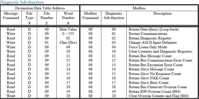
1.4 MODBUS DIAGNOSTIC COMMANDS USING PLC-5 TYPED READ / WRITE COMMANDS
When using PLC-5 Typed Read / Write commands, the Diagnostic commands have the following PLC-3 address format:
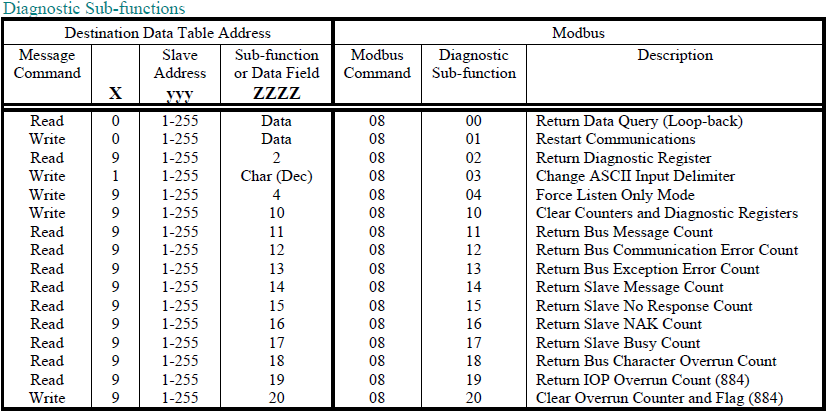
DXyyy:ZZZZ
1.5 PLC-3 WORD RANGE COMMANDS (PLC-3’s and 5’s)
Use the PLC-3 Word Range Read and Write commands whenever possible because the larger address field of these
commands provides the additional flexibility necessary to generate the full range of Modbus commands and
addresses.
On receiving a PLC-3 Word Range Read or Word Range Write Message Command (MC) a DL3500 Modbus Master decodes the command’s Destination Data Table Address (DDTA) File type (character). Then, dependent on whether the PLC message is a read or a write it can generate the appropriate Modbus command as shown in the table below.
Note : For Modbus command 05, set the first word of data in the PLC data table to FF00 (hex) to turn the coil ON and 0000 to turn the coil OFF.
Example 1: B18:30 (xy:z) will access register 00030 from Modbus Slave address 18.
B18:30 ⇒ x = B (File Type), y = 18 (Slave address 18), z = 30 (Register address).
This is an example of message command (PLC3 Word range Write) you may write using your ControlLogix.
Your starting register address for this example is 30.
To configure everything follow the same step as example 1 (Format NXYY:Z) below, and map the register 18 to DL3500.
Example 2 : N200:430 (xy:z) will access register 40430 from Modbus Slave address 200.
N200:430 ⇒ x = N (File Type), y = 200 (Slave address 200), z = 430 (Register address).
Your starting register address for this example is 430.
To configure everything follow the same step as example 1 (Format NXYY:Z), and map the register 200 to DL3500.
Example 3: N240:999 (xy:z) will access register 40999 from Modbus Slave address 240.
N240:999 ⇒ x = N (File Type), y = 240 (Slave address 200), z = 999 (Register address).
Your starting register address for this example is 999.
To configure everything follow the same step as example 1 (Format NXYY:Z), and map the register 240 to DL3500.
On receiving a PLC-3 Word Range Read or Word Range Write Message Command (MC) a DL3500 Modbus Master decodes the command’s Destination Data Table Address (DDTA) File type (character). Then, dependent on whether the PLC message is a read or a write it can generate the appropriate Modbus command as shown in the table below.
The following DDTA format is used for mapping PLC-3 Word Range
Read/Write commands to Modbus commands:
DXyyy:ZZZZ
DXyyy:ZZZZ
Note : For Modbus command 05, set the first word of data in the PLC data table to FF00 (hex) to turn the coil ON and 0000 to turn the coil OFF.
Example 1: B18:30 (xy:z) will access register 00030 from Modbus Slave address 18.
B18:30 ⇒ x = B (File Type), y = 18 (Slave address 18), z = 30 (Register address).
This is an example of message command (PLC3 Word range Write) you may write using your ControlLogix.
Your starting register address for this example is 30.
To configure everything follow the same step as example 1 (Format NXYY:Z) below, and map the register 18 to DL3500.
Example 2 : N200:430 (xy:z) will access register 40430 from Modbus Slave address 200.
N200:430 ⇒ x = N (File Type), y = 200 (Slave address 200), z = 430 (Register address).
Your starting register address for this example is 430.
To configure everything follow the same step as example 1 (Format NXYY:Z), and map the register 200 to DL3500.
Example 3: N240:999 (xy:z) will access register 40999 from Modbus Slave address 240.
N240:999 ⇒ x = N (File Type), y = 240 (Slave address 200), z = 999 (Register address).
Your starting register address for this example is 999.
To configure everything follow the same step as example 1 (Format NXYY:Z), and map the register 240 to DL3500.
1.6 MODBUS DIAGNOSTIC COMMANDS USING PLC-3 WORD RANGE R/W COMMANDS
2.0 DH+/MODBUS SLAVE PROTOCOL USING CONTROLLOGIX
The DL3500-DH+ (or other device on DH+) Modbus Slave module facilitates communication between a Modbus
Master and an Allen-Bradley DH+ network. It provides for serial communications to Modbus with RS232C, RS232
or RS422/RS485 interface capabilities. Interface cable drawings are located in section 3. Communication between
Modbus and the DL3500-DH+ can only be initiated from a Modbus Master (not from the DH+).
The Modbus serial port on the DL3500-DH+ is transparent to Modbus and does not require an address. The DH+ network side of the DL3500 unit is an active station on the DH+ and requires its own DH+ address that must be different than the DH+ station address(es) that the Modbus Master needs to communicate with.
A Modbus Master can read and write to any SLC on DH+ that can handle PLC5 message commands without the need for any programming in the SLC, however the PLC addresses used must not be “protected" and the full range of addresses that the Modbus Master requires to read from or write to must have been previously created in the SLC's data Table. Modbus read and write bit/coil commands are used with A-B SLC Binary (B) files and Modbus read and write word/register commands are used with A-B SLC’s Integer (N) files.
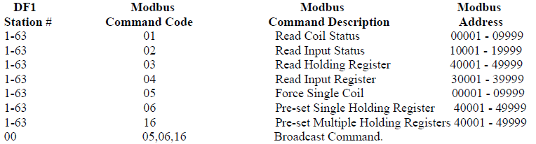
2.1 MODBUS COMMAND CAPABILITIES
The Equustek’s product firmware module is compatible with the following Modbus commands: -
2.2 BROADCAST COMMAND
Modbus protocol uses the Broadcast command (i.e. commands 05, 06 and 16 with a station address of 00) to write to
all slave devices on a Modbus network simultaneously, no response is expected by the Master. Allen-Bradley DH+
protocol does not support Broadcast. A-B SLC’s are not capable of responding to a single "Broadcast" command
over the DH+ network. DL3500s can be configured to ignore or to execute Broadcasts. Broadcasting is
accomplished by splitting the command into separate messages for retransmission one at a time to each DH+ station
within pre-configured range of stations. Because of the time taken to send out multiple messages over the DH+,
Broadcasts commands are normally restricted to an absolute minimum range of DH+ stations.
A SLC or other device at DH+ station address 00 cannot be addressed by Modbus read or write commands as 00 is normally the Broadcast command. DH+ station 00 may be used as the DH+ station address for the DL3500.
NOTES :
1. Restrict the DH+ stations receiving a Modbus broadcast to prevent writing to unintended DH+ destinations.
2. Valid Modbus Slave addresses of stations on DH+ are 1 to 77 octal (i.e. Slave station addresses 1 to 63 dec.).
2.3 COMMUNICATIONS SEQUENCE
The DL3500 module receives a Modbus query on its asynchronous serial port, converts it into the appropriate DH+
message and sends it out on the DH+ network. The DH+ response is received, converted into the corresponding
Modbus response and sent back to the Modbus Master. Modbus protocol does not allow messages to be buffered so
the DL3500 processes one message at a time. The DL3500 unit will respond to the Modbus interface with the
appropriate Modbus exception codes in the event of detectable errors.
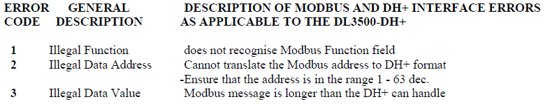
2.4 MODBUS EXCEPTION CODE RESPONSES
2.5 MODBUS MESSAGE DATA LENGTH CONSIDERATIONS
The following shows the maximum number of coils/registers that can be sent or received in a single Modbus
message. The limits are because of the different structure of Modbus and A-B DH+ protocols, and also due to the
internal memory structure of the DL3500. These values have only a limited relationship to the Modbus/DH+
address mapping ranges configured in the DL3500.
• The max. number of coils that can be read in a single transaction is 1600. (Normal Modbus allows 2000)
• The max. number of registers that can be read in a single transaction is 100. (Normal Modbus allows 125)
• The max. number of registers that can be written in a single transaction is 100. (Normal Modbus allows 100)
CAUTIONS:
1. Ensure that your communications program design prevents self-optimising Modbus Master communications programs (in some MMIs and Operator Interfaces) from requesting data in packets larger than the above limits.
2. Ensure that the Modbus program does not generate Modbus commands with addresses that can bridge across more than one of the address range entries configured in the DL3500.
3. Any of the above conditions could cause indeterminate errors.
2.6 MODBUS TO DH+ - GENERAL OVERVIEW
The DL3500 unit is transparent to valid Modbus commands addressed to station numbers corresponding to active
stations on DH+. The DL3500 will only accept commands to DH+ station addresses 1 to 63 decimal. Modbus
commands using address 0 are broadcast commands and are handled differently by the DL3500.
After formatting and converting the Modbus message to DH+ protocol the command is sent out to the addressed DH+ (slave) device. If the station is inactive the query is disregarded. Each addressed slave station must be a unique address on Modbus and on the DH+ network (i.e. do not duplicate an address used on the Modbus network with a station address on the DH+). If duplicate addresses exist then the situation will arise where two or more stations could accept the query resulting in multiple responses which would cause communications errors and perhaps writing to unintended destinations.
NOTE:
Special consideration should be given to the Modbus and DH+ addressing to avoid duplication of network addresses. Confusion could arise because A-B uses an "octal" addressing scheme for DH+ network stations and Modbus uses "decimal". Ensure use of a common numbering scheme (see section 1.6 for cross-references).
2.7 MODICON MODBUS TO A-B PLC ADDRESS MAPPING
The relationship between Modicon Modbus and Allen-Bradley PLC addresses is programmed by the user and is
stored in the DL3500's EEPROM. The DL3500 can be programmed for eight different address ranges. Each
Modicon address range that you wish to set-up may be mapped to a unique A-B address range. The length of the AB
field required is the same as that defined by the Modicon address range. All A-B files should be either Binary,
Integer or Floating Point files. These A-B files must be created by the A-B PLC programmer to the full length
required by the Modbus Address Translation and Mapping parameters specified. No logic is needed in the A-B PLC
to respond to commands received from the Modbus network. To define how a range of Modicon addresses maps
over to Allen-Bradley addresses, the user must enter the following configuration information:
In the configuration software the type of PLC used is selected. See below.
 Modbus Parameters-DL32
V3.1
Modbus Parameters-DL32
V3.1
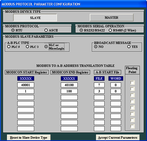
In the configuration software the type of PLC used is selected. See below.
Modbus Parameters-DL32
V3.12.7.1 DEFINITION OF MODBUS SLAVE PARAMETER SCREEN
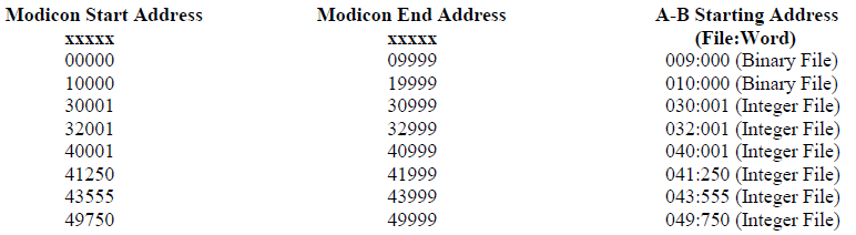
Modicon Start Address :
Specifies the starting address of a range of Modbus addresses that will be mapped to A-B. Valid entries are 00000 to 09999, 10000 to 19999, 30001 to 39999 and 40001 to 49999.
Modicon End Address :
Specifies the end address of a range of Modbus addresses that will be converted to A-B. The range of entries is shown above.
A-B Starting Address :
Specifies the A-B PLC starting file number for the Modbus data. Valid entries are 001:000 to 999 : 999 (Sometimes files less than 8 are reserved) (ensure that data length does not exceed file boundary). NOTE: N7 and B3 are valid files!! Floating Point Checkbox: Used to Specify if the data is Modbus Floating point and to be written into Floating Point Files
Coils/discretes:
The bit address range of an A-B Binary file is 1000 words or 16,000 bits (i.e. 0 - 15,999 decimal). This means that one A-B file is more than sufficient to hold the largest Modbus coil address possible. An A-B binary file/bit address starts at bit 0 and the first “legal” Modbus coil address starts at 1, which means that normally the first Modbus coil address 00001 (or 10001) will correspond to bit 0 in A-B word 0. If a Modbus address of 00000 (or 10000) is entered in the Starting Address field it causes the first (legal) Modbus coil addresses i.e. bit 1 to correspond to an A-B file/word bit 1. This technique makes it easy to compare and match the Modbus and A-B memory maps, and easier to bit search the A-B program. When a Modbus coil /bit address is defined in the Start Address field i.e. 0XXXX or 1XXXX), then the first A-B Starting Address that can be used is Binary file 3 word 000 (B3:0).
Registers/words:
The word address range of an A-B Integer file is 0 - 999 i.e., only 1000 words (registers). Therefore if a Modbus address range greater than 1000 registers is required, it is necessary to use more than one A-B Integer (N) file, which will require multiple configuration parameter entries. The first A-B address that can be used for 3xxxx and 4xxxx register/word transfers is an A-B Integer file at file/word address N7:0.
Address Ranges:
The Modicon Address Range (i.e., Start Address less End Address), and the A-B Start Address selected, must not overflow the maximum A-B file address limit. This means that if A-B Starting Address of word 250 is used then the maximum register range for mapping must be 1000 minus 250, i.e. 750.
2.7.2 MODICON TO AB ADDRESS MAPPING EXAMPLE
Example 1 Integer Files
Mapping Modicon registers 40001 to 40010 to A-B file N7:0 to N7:9
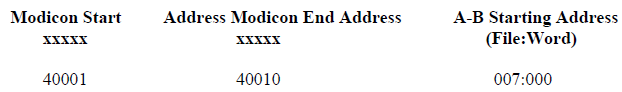
Now make sure you map every A-B starting Address with a tag in your ControlLogix. For this example we should have: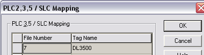
If you want to know how to configure your ControlLogix, just follow example 1 shown in Modbus master protocol using ControlLogix.
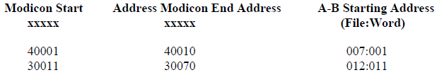
Example 2(*) Integer Files
Mapping Modicon registers 40001 to 40010 to A-B file N7:1 to N7:10
Mapping Modicon registers 30011 to 30070 to A-B file N12:11 to N12:70
Note: (*)
This technique makes it easy to compare and match the Modbus and A-B memory maps, and easier to bit search the A-B program.
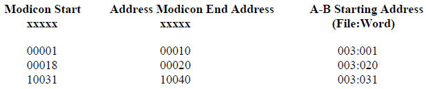
Example 3 Binary Files
Mapping Modicon coils 00001 to 00010 to A-B file B3/48 (binary file B3, bit 48) to B3/57
Mapping Modicon coil 00020 to A-B file B3/98
Mapping Modicon coils 10031 to 10040 to A-B file B3/32 to B3/41

NOTE:
When mapping a Modicon coil to an A-B PLC bit that does not start at bit 0 of a word, an offset to bit 0 must be added.
Example 4 Binary Files
Mapping Modicon coils 00001 to 00010 to A-B file B3/16 (binary file B3, bit 16) to B3/25
Mapping Modicon coil 00020 to A-B file B3/320
Mapping Modicon coils 10031 to 10040 to A-B file B3/496 to B3/505
Example 5 Floating Point Files
Mapping Modicon registers 40001 to 40002 to A-B file F8:0
Mapping Modicon registers 30001 to 30010 to A-B file F8:5 to F8:9
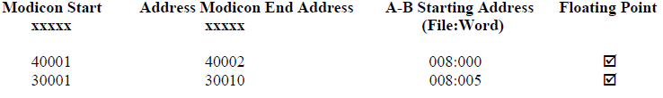
NOTE :
A-B Floating Point (F) values are 32 bits in length and require two Modbus registers for each floating point value.
NOTES:
1. The (Binary File) and (Integer File) text after the A-B File:Word address does not appear on the configuration screen and is provided here for reference only.
2. The A-B file corresponding to Modbus Coil addresses should have been previously configured in the PLC as a Binary (B) file and its size configured for the largest coil address.
3. The A-B file corresponding to Modbus Register addresses should have been previously configured in the PLC as an Integer (N) file and its size configured for the largest register address.
Mapping Modicon registers 40001 to 40010 to A-B file N7:0 to N7:9
Now make sure you map every A-B starting Address with a tag in your ControlLogix. For this example we should have:
If you want to know how to configure your ControlLogix, just follow example 1 shown in Modbus master protocol using ControlLogix.
Example 2(*) Integer Files
Mapping Modicon registers 40001 to 40010 to A-B file N7:1 to N7:10
Mapping Modicon registers 30011 to 30070 to A-B file N12:11 to N12:70
Note: (*)
This technique makes it easy to compare and match the Modbus and A-B memory maps, and easier to bit search the A-B program.
Example 3 Binary Files
Mapping Modicon coils 00001 to 00010 to A-B file B3/48 (binary file B3, bit 48) to B3/57
Mapping Modicon coil 00020 to A-B file B3/98
Mapping Modicon coils 10031 to 10040 to A-B file B3/32 to B3/41
NOTE:
When mapping a Modicon coil to an A-B PLC bit that does not start at bit 0 of a word, an offset to bit 0 must be added.
Example 4 Binary Files
Mapping Modicon coils 00001 to 00010 to A-B file B3/16 (binary file B3, bit 16) to B3/25
Mapping Modicon coil 00020 to A-B file B3/320
Mapping Modicon coils 10031 to 10040 to A-B file B3/496 to B3/505
Example 5 Floating Point Files
Mapping Modicon registers 40001 to 40002 to A-B file F8:0
Mapping Modicon registers 30001 to 30010 to A-B file F8:5 to F8:9
NOTE :
A-B Floating Point (F) values are 32 bits in length and require two Modbus registers for each floating point value.
NOTES:
1. The (Binary File) and (Integer File) text after the A-B File:Word address does not appear on the configuration screen and is provided here for reference only.
2. The A-B file corresponding to Modbus Coil addresses should have been previously configured in the PLC as a Binary (B) file and its size configured for the largest coil address.
3. The A-B file corresponding to Modbus Register addresses should have been previously configured in the PLC as an Integer (N) file and its size configured for the largest register address.
2.7.2 ADDRESS MAPPING LIMITATIONS AND PRACTICES
Modbus protocol generally permits a maximum of about 125 registers or 2000 coils to be read in a single transaction
(the maximum number is dependent on the Modbus driver). When specifying multiple address translation ranges
within the same type of Modbus address (either Oxxxx, 1xxxx, 3xxxx or 4xxxx) it is essential to establish a buffer
region of at least 125 registers or 2000 coils between each address type’s range. Failure to do this may allow a selfoptimising
MMI interface program to write (or read) data to/from two different areas of the Allen-Bradley PLC with
undesired and indeterminate results.
The examples above define a similar A-B word address to the Modbus start address which allows easier comparison between the Modbus A-B addresses used. For example a Modbus start address of 40001 can be represented in A-B PLC-5 file format by using A-B integer file N 40:001. Address mapping using this technique is recommended for a user’s convenience only, as it provides a very useful method for record-keeping, cross-reference and recognition. This technique is not mandatory and any Modbus address can be written to any A-B file.
When considering use of the above technique note that the first available open A-B file address for a PLC-5 controller is file 7. Modbus address 0xxxx cannot be displayed similarly in A-B format as A-B output file 0 should not be used. In this case for easy recognition use an A-B Binary file for Modbus output coils such as 9, 99, 999 or any other convenient file number is easily recognizable.
DL4000 firmware permits the entry of 00000 and 10000 values in the Modicon Start Address field even though strictly speaking these are not legal Modbus addresses. This feature allows a programmer to align an A-B Binary file bit 1 with the first legal Modbus Bit / Coil address 1. For example mapping Modicon Start Address 00000 to A-B Start Address (B) 003:000, or Modicon Start Address 10000 to A-B Start Address (B) 010:000 aligns Modbus bit 1 with A-B bit 1. The "B" for Binary file is implied but not displayed.
NOTES:
1. Enough space must have been configured and be available in the A-B file to contain the full
range of Modbus addresses specified or it will cause over-writing existing A-B files and data.
2. Do not transmit Modbus messages to the DL4000 to read or write more than 1600 coils or 100 registers in a single Modbus read or write command.
3. Ensure that all A-B addresses specified have been created in the destination PLC.
4. Set all unused Modbus to A-B addresses to zero.
2. Do not transmit Modbus messages to the DL4000 to read or write more than 1600 coils or 100 registers in a single Modbus read or write command.
3. Ensure that all A-B addresses specified have been created in the destination PLC.
4. Set all unused Modbus to A-B addresses to zero.