PDF Download
The Proud Company
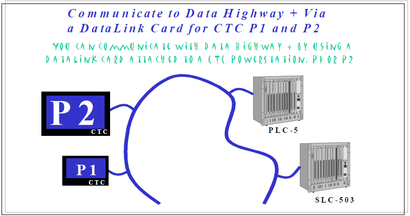
Interact to Data Highway + Via a DataLink Card for P1 or P2
These instructions pertain to communicating via a DataLink card to a Data Highway Plus
Network using a CTC P1 or P2.
The hardware and software necessary is defined below :
HARDWARE
→ 1-P1 or P2 PowerStation from CTC. In our example, we are using a P1.
→ 1-PC/104 Installation Kit from CTC for a P1 or P2. Installation Guide Included.
→ 1-DataLink PC-104 card with User’s Guide.
→ 1-Download cable for DataLink card. See DataLink Users Guide for Pin-outs.
→ 1-Data Highway Plus Cable known as the “Blue Hose”.
→ 1-PC or Laptop with Windows 95 or NT installed and an open Com port
SOFTWARE
→ In this example, we will be communicating to a PLC-5 model 30 PLC from Allen-Bradley.
→ These instructions assume that the PLC has been programmed. In this example, PLC-5 6200 software version 4.4 was used.
→ Several rungs of ladder logic were inserted using the addresses below:
- Bit 3.4 – Bit 3.5
– Bit 3.11 – Word 3:10 - Word 3:12 -
- Bit 3.6 – Bit 3.7
- Timer in Word 3:4 -
- Word 3:1 - Word 3:2
→ CTC Interact version 5.2 is being used..
→ DataLink configuration software. Version 32.021 for Windows 95/NT was used.
→ The Allen-Bradley Data Highway(ABDH) device driver that is included with the CTC Interact software will be used.
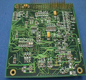
Figure A. Front
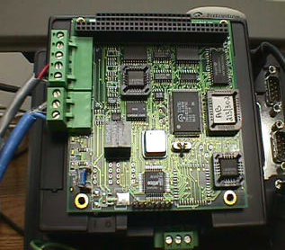
Figure B. Back
Interact to Data Highway + Via a DataLink Card for P1 or P2
The instructions will be separated into different sections.
HARDWARE
Part I – Installing the Hardware
SOFTWARE
Part II – Configuring the DataLink Card.
Part III – Creating an Interact Application and Loading the Modules and Drivers.
Part IV – Configuring the Allen-Bradley Data Highway Driver.
Part V – Configuring the Communication Port Within Interact.
Part VI – Building a screen and addressing the Panel Tools.
Datalink Card shown above in Figure A and B.
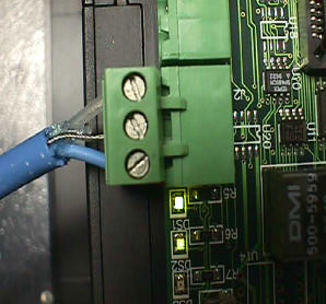
Figure C. 3-Pin Phoenix Connector – DH+
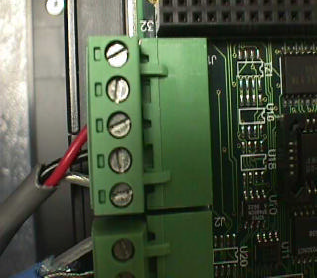
Figure D. 5-Pin Phoenix Connector – Download
Interact to Data Highway + Via a DataLink Card for P1 or P2
The instructions will be separated into different sections.
HARDWARE
Part I – Installing the Hardware
Step 1 ) Using the CTC P1 or P2, install the PC/104 expansion adapter using the Installation Guide that is included with the installation kit.
Step 2 ) Install the DataLink card into the PC/104 expansion adapter using the DataLink User’s Guide.
Step 3 ) Insert the DH+ cable(the “Blue Hose”) into the 3-Pin DH+ connector of the DataLink card as shown in Figure C. Connect the other end of the “Blue Hose” to a data highway plus port.
Step 4 ) Insert the DataLink Download cable into the 5-Pin connector of the DataLink card as shown in Figure D. Connect the other end of the download cable into one of the Com ports of the PC or laptop where the DataLink software will be installed.
Please make note of the communication port that is used in Step 4, since you will need this information during the software configuration of the DataLink card.
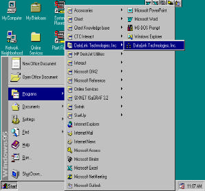
Figure E. Navigate to DataLink software icon
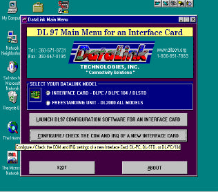
Figure F. DataLink Main menu
Interact to Data Highway + Via a DataLink Card for P1 or P2
The instructions will be separated into different sections.
Software
Part II – Configuring the DataLink Card.
Step 1 ) Use the DataLink Installation diskettes to install the configuration software on the PC or laptop that you are using. Run SETUP.EXE from RUN option of the Windows 95/NT Start menu.
After software installation is complete, start the software by navigating to the DataLink Technologies icon. Figure E shows how to do this.
Step 2 ) Select the Windows START menu.
Step 3 ) Select the Programs menu option.
Step 4 ) Select the DataLink Technologies, Inc menu option.
Step 5 ) Select the DataLink Technologies, Inc icon.
When the configuration software has started, the main menu should appear similar to Figure F.
Step 6 ) Select the Configure/Check the Com and IRQ of a New Interface Card menu option.
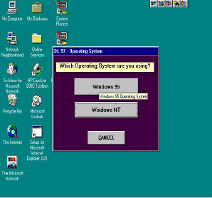
Figure G.
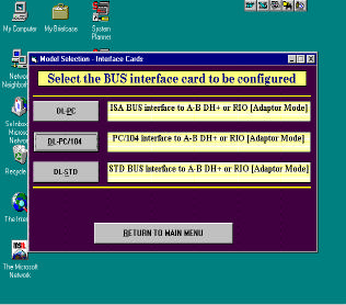
Figure H.
Interact to Data Highway + Via a DataLink Card for P1 or P2
Software
Part II – Configuring the DataLink Card (continued).
Step 7 ) Select the operating system of the computer or laptop that you are using (Figure G). For our example, the Windows 95 option was selected.
Step 8 ) Select the DL-PC/104 option from the BUS interface configuration screen (Figure H). This option was selected because we are using a PC/104 interface to Allen Bradley Data Highway Plus.
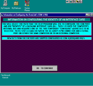
Figure I.
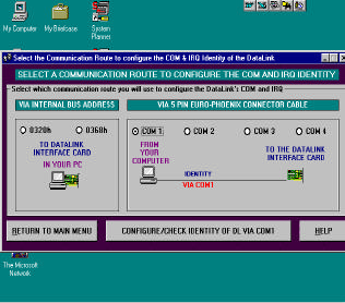
Figure J.
Interact to Data Highway + Via a DataLink Card for P1 or P2
Software
Part II – Configuring the DataLink Card(continued).
Step 9 ) Select the [OK – TO CONTINUE] button on the bottom of the screen shown in figure I after reading the information given. This information talks about the Com port and IRQ settings that come with all Datalink cards by default. The defaults are Communication port COM4 (02E8) and IRQ 5. CTC Interact easily communicates with the Datalink card using these settings. If these settings are changed, problems may occur. The screen from Figure J will allow you to tell the software what Com port that you will be using to configure the DataLink card.
Step 10 ) On the right hand side of the screen under the VIA 5 PIN EURO-PHOENIX CONNECTOR CABLE heading, select the communication port of the PC or laptop that is connected to the DataLink card. In the example above, COM 1 was selected.
Step 11 ) Select the [RETURN TO MAIN MENU] button.
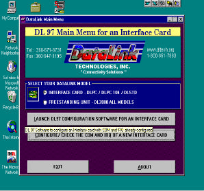
Figure K.
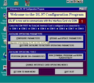
Figure L.
Interact to Data Highway + Via a DataLink Card for P1 or P2
Software
Part II – Configuring the DataLink Card(continued).
Step 12 ) From the main menu, select the Launch DL97 Configuration Software for an Interface Card option as shown in figure K.
Step 13 ) The Select the BUS interface card to be configured screen. This is the same screen from Step 8. Select the DL-PC104 option once again.
Step 14 ) The DL97 Configuration Program screen will appear.
Be sure to verify that the communication port that was selected from Step 10 is listed in the upper right hand corner of the screen. If the communication port that you selected does not match what is on this screen, then you must return to the beginning of the Configuring the DataLink Card and start again.
Select the [Configure Parameters] button.
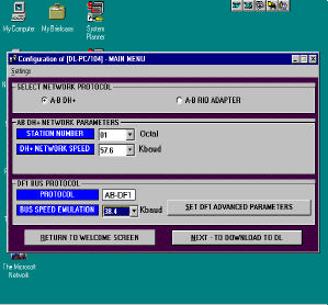
Figure M.
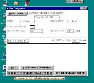
Figure N.
Interact to Data Highway + Via a DataLink Card for P1 or P2
Software
Part II – Configuring the DataLink Card (continued).
Step 15 ) Figure M shows the Main Menu of the configuration screen. Select the A-B DH+ option as the network protocol.
Step 16 ) Select the Station number and DH+ Network speed. In our example station number 01 was used and the network speed was left at the default value of 57.6. The number of other nodes on the DH+ Network may have an impact on the Station Number that is used.
The rest of the options should be left at their default value.
Step 17 ) At this point, the configuration settings are ready to be downloaded to the DataLink card. Select the [NEXT-TO DOWNLOAD TO DL].
Step 18 ) A configuration confirmation screen appears similar to Figure N above. After verifying that the data on this screen matches the configuration from the previous screen, select the flashing [CLICK HERE TO DOWNLOAD PARAMETERS TO DL] button.
The configuration of the DataLink card is now complete.
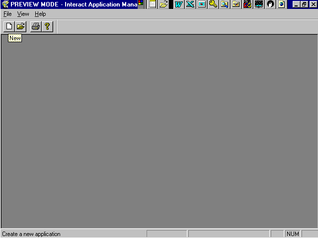
Figure O.
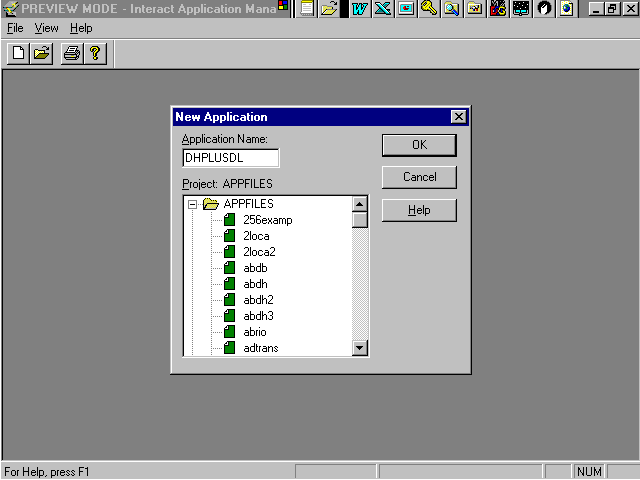
Figure P.
Interact to Data Highway + Via a DataLink Card for P1 or P2
Software
Part III – Creating an Interact application and loading the modules and drivers.
Step 1 ) Start a new application by opening up Interact Development and selecting the New icon as shown in Figure O. Another option is to select the File menu option and then select the New Application option.
By doing this, a window will appear as shown in Figure P.
Step 2 ) Type in the name of the application that you wish to create.
In the example above, DHPLUSDL is the application name.
Step 3 ) Select the [OK] button.
Figure O.
Figure P.
Interact to Data Highway + Via a DataLink Card for P1 or P2
Software
Part III – Creating an Interact application and loading the modules and drivers.
Step 1 ) Start a new application by opening up Interact Development and selecting the New icon as shown in Figure O. Another option is to select the File menu option and then select the New Application option.
By doing this, a window will appear as shown in Figure P.
Step 2 ) Type in the name of the application that you wish to create.
In the example above, DHPLUSDL is the application name.
Step 3 ) Select the [OK] button.
Part III – Creating an Interact application and loading the modules and drivers.
Step 1 ) Start a new application by opening up Interact Development and selecting the New icon as shown in Figure O. Another option is to select the File menu option and then select the New Application option.
By doing this, a window will appear as shown in Figure P.
Step 2 ) Type in the name of the application that you wish to create.
In the example above, DHPLUSDL is the application name.
Step 3 ) Select the [OK] button.
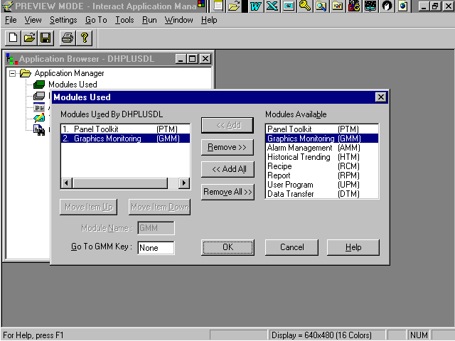
Figure Q.
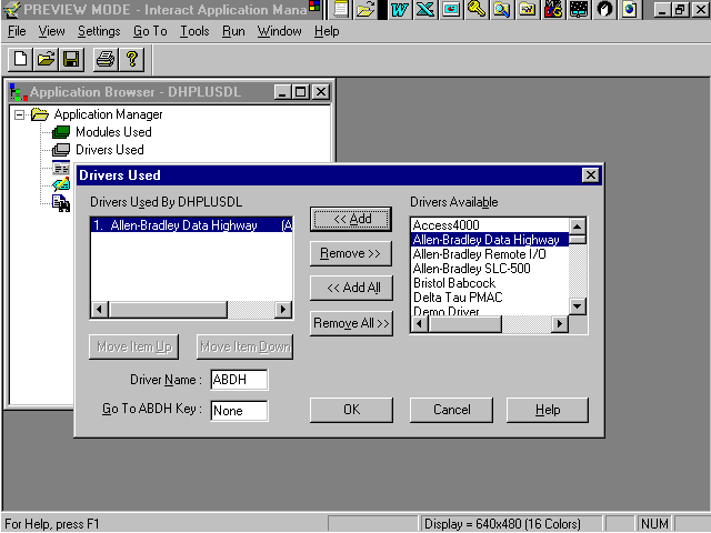
Figure R.
Interact to Data Highway + Via a DataLink Card for P1 or P2
Software
Part III – Creating an Interact application and loading the modules and drivers(cont).
To load a module or modules within Interact
Step 4 ) Double-click on Modules Used option under the Application Manager.
A window will appear. On the left side, a blank listing box will appear with a heading above it as Modules Used By {Application Name from Step 3}. On the right side of the window, all the available modules within Interact will appear in the box labeled Modules Available. A column of buttons to add and remove modules separates these two listings.
Step 5 ) Highlight (by single-clicking) the module name in the Modules Available listing and selecting the [<<ADD] button. After selecting all the modules to be loaded, select the [OK] button.
This process will copy the module that you highlighted into the Modules Used box. In the above example (Figure Q), two modules, the Panel Toolkit module(PTM) and the Graphics Monitoring module(GMM) were loaded.
To load a driver or drivers within Interact
Step 6) Double-click on Drivers Used option under the Application Manager.
A window will appear similar to the Modules Used window.
Step 7) Highlight (by single-clicking) the driver name in the Drivers Available listing and selecting the [<<ADD] button. After selecting all the drivers to be loaded, select the [OK] button.
This process will copy the drivers that you highlighted into the listing of Drivers Used. In the above example (Figure R), the Allen-Bradley Data Highway (ABDH) driver was loaded.
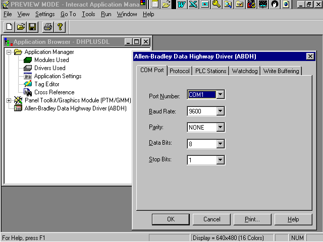
Figure S.
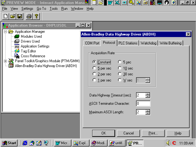
Figure T.
Interact to Data Highway + Via a DataLink Card for P1 or P2
Software
Part IV – Configuring the Allen-Bradley Data Highway Driver.
After loading the driver, an icon will appear under the Application Manager labeled Allen- Bradley Data Highway (ABDH). To configure the driver:
Step 1 ) Double-click on the icon labeled Allen-Bradley Data Highway (ABDH).
The Allen-Bradley Data Highway configuration pop-up window will appear. This window should contain 5 tabs as shown in Figure S. The tabs are titled, 1) COM Port, 2) Protocol, 3) PLC Stations, 4) Watchdog, 5) Write Buffering.
The complexity of your application will determine which tabs need to be configured. In our basic example, we will only be concerned with the first three tabs. The definition of each field within the tabs can be found by selecting the [HELP] button on the bottom of the configuration window.
Step 2 ) On the COM Port tab, change the Port Number to the communication port that the cable is connected to from Step 1. COM 1, 2, 3 or 4 are the options. The other settings are the default settings and should be left alone.
Step 3 ) Select the Protocol tab.
For the example above (figure T), the default values for Acquisition Rate, Data Highway Timeout, ASCII Terminator Character and Maximum ASCII Length are sufficient.
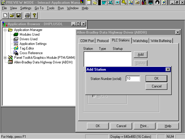
Figure U.
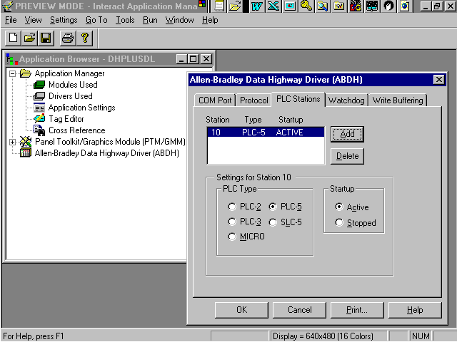
Figure V.
Interact to Data Highway + Via a DataLink Card for P1 or P2
Software
Part IV – Configuring the Allen-Bradley Data Highway Driver(cont).
Step 4 ) Select the PLC Stations tab.
To set up the station:
Step 5 ) Select the [Add] button.
A window will appear similar to figure U where you input the Station Number in octal. In the above example, station number 10 was used.
The station number must match the PLC node address. There are two different ways to find out what address a PLC is configured for: 1) by looking at the dip switches on the PLC hardware and 2) by navigating into the Channel Configuration screen within the A-B PLC programming software.
Step 6 ) Select the [OK] button.
At this point the station has been added to the Station Listing box as shown in FigureV. You have the option to define the type of PLC and whether the PLC is active during startup or not.
Step 7 ) Select the PLC-5 option as the PLC type.
Step 8 ) Select the Active as the Startup option.
Step 9 ) Select the [OK] button since no other tabs need to be configured for our basic application.
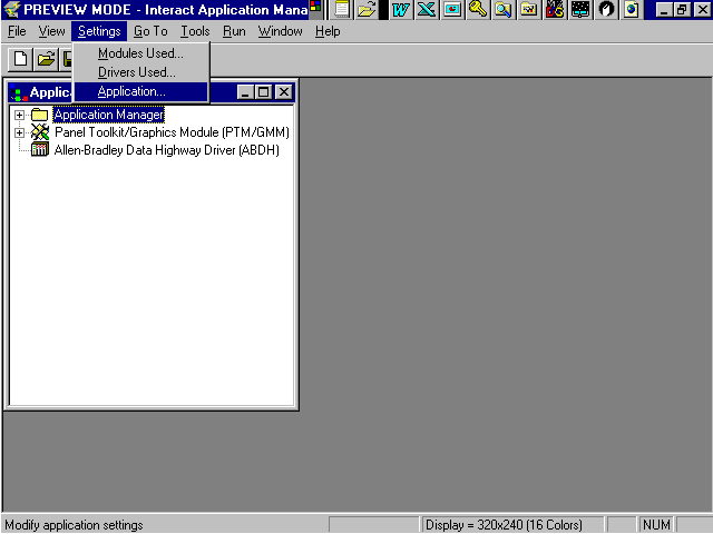
Figure W
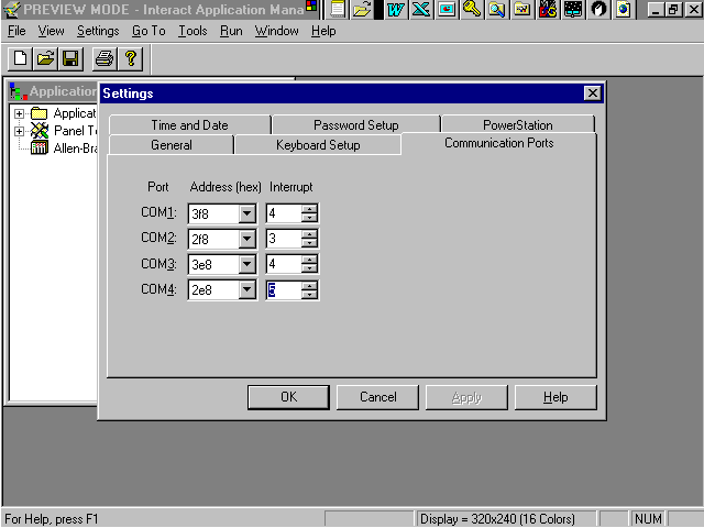
Figure X
Interact to Data Highway + Via a DataLink Card for P1 or P2
Software
Part V – Configuring the Communication Port Within Interact
Navigate into the Interact Application Settings by:
Step 1 ) Select the Application Manager.
Step 2 ) Select the Settings menu option from the tool bar(figure W).
Step 3 ) Select the Application option.
A window will appear similar to figure X showing the Settings configuration tabs.
Step 4 ) Select the [Communication Ports] tab(figure X).
Similar to step 9 of section II, Configuring the Data Link Card, communication port 4 should be set to IRQ 5.
Step 5 ) Set the Interrupt for COM4 to 5.
Interact to Data Highway + Via a DataLink Card for P1 or P2
Software
Part VI – Building the screen and addressing the panel tools.
It is time to build a screen or panel.
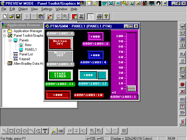
On the screen shown above, there are a series of push buttons, indicators, numeric displays, slides, numeric entries and panel labels put together.
Above or below each tool is a panel label that defines the address that is being used by the tool. These addresses were referenced on the first page of this packet.
Part VI – Building the screen and addressing the panel tools.
It is time to build a screen or panel.
On the screen shown above, there are a series of push buttons, indicators, numeric displays, slides, numeric entries and panel labels put together.
Above or below each tool is a panel label that defines the address that is being used by the tool. These addresses were referenced on the first page of this packet.

Interact to Data Highway + Via a DataLink Card for P1 or P2
Software
Part VI – Building the screen and addressing the panel tools. (cont)
After building a screen or panel, the last thing remaining is to address the tools.
Step 1 ) Double-click on any of the tools that you have used.
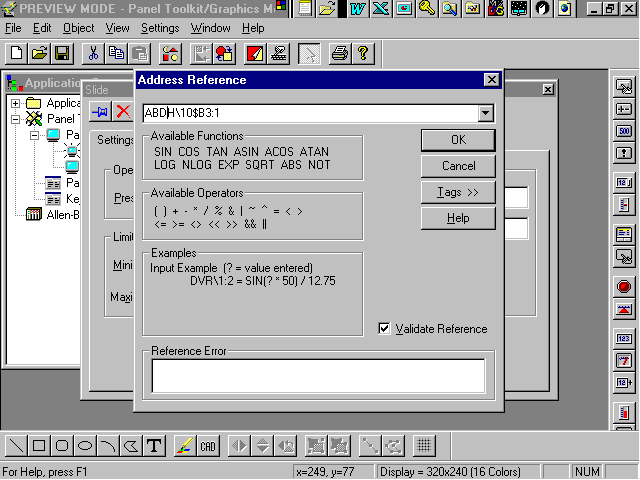
A tool configuration window will appear with the Settings tab active. Somewhere within this tab(depending on the tool that was used) will appear an Address Reference box.
Step 2 ) Single-click within the Address Reference box and a window will appear similar to the above figure. This is where you put in the PLC address that you wish to use.
In Appendix A, the address format definitions are detailed for the PLC-5 from Allen-Bradley. Step 3 ) Select the [OK] button.
After all the tools have been addressed you are ready to run your application. Enjoy.
Part VI – Building the screen and addressing the panel tools. (cont)
After building a screen or panel, the last thing remaining is to address the tools.
Step 1 ) Double-click on any of the tools that you have used.
A tool configuration window will appear with the Settings tab active. Somewhere within this tab(depending on the tool that was used) will appear an Address Reference box.
Step 2 ) Single-click within the Address Reference box and a window will appear similar to the above figure. This is where you put in the PLC address that you wish to use.
In Appendix A, the address format definitions are detailed for the PLC-5 from Allen-Bradley. Step 3 ) Select the [OK] button.
After all the tools have been addressed you are ready to run your application. Enjoy.
APPENDIX
A
PLC-3, PLC-5, SLC-500 Addressing Format
This topic describes the addressing format used with PLC-3, PLC-5, and SLC-500 controllers. Select the
below link to navigate to a specific area of interest:
The address format when using a PLC-3 or PLC-5 is:
driver_name \ s $ m f : o . b
The address format when using a SLC-500 is:
driver_name \ s $ m f : e . u, b
driver_name - defaults to ABDH, but you can change the name through a selection on the Application Manager menu.
\ - Delimiter that separates driver name from PLC station number
s - PLC station number, 0-376 octal
$ - Delimiter that separates station number from memory type
m - memory type. 1 or 2 letters listed on a following screen.
f - file number. Up to 3 numbers listed on a following screen.
: - Delimiter that separates file and offset number o - offset number (PLC-3, PLC-5)
0-7777 octal for I/O memory (memory types I and O)
0-9999 decimal for all other memory types
e - element number (SLC-500)
0-30 decimal for input and output types
0-32 decimal for status types
0-255 decimal for all other memory types
. - Delimiter that separates offset and bit numbers (PLC-3 and PLC-5) or delimiter that separates element
and sub-element numbers (SLC-500)
u – sub-element number (SLC-500)
0-9999 decimal
, - delimiter that separates element or subelement numbers and bit numbers (SLC-500
) b - bit number (optional)
0-17 octal for PLC-5 I and O memory types and all PLC-3 memory types.
0-15 decimal for all other PLC-5 memory types.
1-128 decimal for ASCII data types (1 - 82 for Native String (ST) types).
PLC-3, PLC-5, SLC-500 Addressing Format (continued)
Note: The bit number is used for the number of characters in the string for the ASCII data type. If omitted,
the string length for read operations will default to the Maximum ASCII Length.
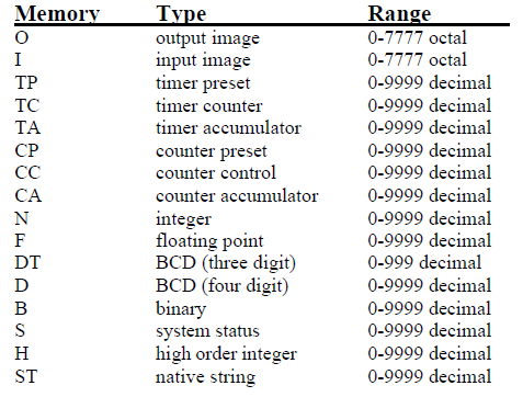
Memory Types
 Floating point (F) and high order integer (H) memory types do NOT support bit addressing. If a bit number
is used with these memory types, a question mark (?) will be placed over the tool upon entering the Run
mode.
Floating point (F) and high order integer (H) memory types do NOT support bit addressing. If a bit number
is used with these memory types, a question mark (?) will be placed over the tool upon entering the Run
mode.
Note: The SLC-500 does not support the following types: DT, D or H.
All timer (TP, TC, TA) and counter (CP, CC, CA) memory types support bit addressing for READ tools only. If a bit number is used on a write tool with these memory types, a question mark (?) will be placed over the tool upon entering the Run mode.
Note that D and DT reference the same memory but are interpreted differently.
Note that ST is only supported by the PLC-5 and SLC-500.
The following memory types are supported for the SLC-500 only:
 An ASCII data type modifier (A) can be used with the N (integer) file type. You can not use the ASCII
modifier with any other file type.
An ASCII data type modifier (A) can be used with the N (integer) file type. You can not use the ASCII
modifier with any other file type.
For example: SLC5\1$NA7:2 is displayed as an ASCII string.
Memory Types
Note: The SLC-500 does not support the following types: DT, D or H.
All timer (TP, TC, TA) and counter (CP, CC, CA) memory types support bit addressing for READ tools only. If a bit number is used on a write tool with these memory types, a question mark (?) will be placed over the tool upon entering the Run mode.
Note that D and DT reference the same memory but are interpreted differently.
Note that ST is only supported by the PLC-5 and SLC-500.
The following memory types are supported for the SLC-500 only:
For example: SLC5\1$NA7:2 is displayed as an ASCII string.
PLC-3, PLC-5, SLC-500 Addressing Format (continued)
File Numbers
File numbers 0, 1, and 2 are reserved in the PLC-5, 0 through 8 are reserved in the SLC-500. The PLC-3 enables any file number from 0-999 to be used with any memory type.
0 = output 1 = input
2 = status 3 = bit
4 = timer 5 = counter
6 = control 7 = integer
8 = floating point9-999 = for additional file storage
Mnemonics
The following mnemonics may be used in place of the SUBELEMENT number in a SLC-500.
PRE: preset LEN: length
ACC: accumulator POS: position
For example: ABDH\1$T4:1.PRE
The following mnemonics may be used in place of the BIT number for the SLC-500.
EN: enable bit EM: stack empty bit
CU: count up bit UN: underflow bit
TT: timing bit ER: error bit
EU: unload enable bit UA: update accum bit
CD: count down bit UL: unload bit
DN: done bit IN: inhibit bit
OV: overflow bit FD: found bit
For example: ABDH\1$T4:1,EN
Examples
ABDH\16$N7:2
driver name: ABDH
PLC station number: 16
memory type: N for integer
file number: 7
offset number: 2
ABDH\25$B3:2.5
driver name: ABDH
PLC station number: 25
memory type: B for binary
file number: 3
offset number: 2
bit number: 5