DLPCI
User’s Guide
Revision 1.01 – Sep. 12, 2013
PDF Download
Equustek Solutions, Inc.
Suite 286, 5489 Byrne Rd.
Burnaby, BC, Canada
V5J 3J1
Toll Free: 888-387-3787
www.equustek.com
Table of Contents
4.1 Online Mode of Operation
4
4.2 Offline Mode
4
4.3 BIOS Manager Options
5
5.1 Switch Functions
6
5.2 Indicator Functions
6
5.2.1 Power-Up and Reset Sequence
6
5.2.2 Normal On-line Operation
6
5.2.3 On-Line, Power-Up and Reset Errors
6
5.2.4 Off-Line Modes
7
7.1 DLPCI-DF1 – DF1 to DH-485/DH+ interface
8
1.0 DLPCI General Operation & Applications
The DLPCI continues the functionality of the current DLPC/DLPC104 product line. It offers both the
Allen Bradley DH-485 or DH+ support.
The DLPCI has two communication ports. Channel A is designed to connect to you industrial network, either A-B’s DH+ or DH-485 networks. Channel B is used to connect to your serial DF1 protocol.
Configuration of the operating parameters is done quickly and easily by the DL32 configuration software shipped with the unit or available on the Equustek Website.
Currently there are two standard DLPCI products available to allow access to A-B’s DH-485 and DH+ network. Contact Equustek Solutions to see if the DLPCI is the correct device for your communication needs.
The DLPCI-DF1 is a two port device that allows your DF1 driver to communicate with ones on an Allen Bradley DH-485 or DH+ network. The DF1 model is a direct replacement for the 1770-KF3 for DH-485 and 1770-KF2 for DH+ and allows your PCs access to any node on the corresponding Allen Bradley network.
2.0 Hardware Specifications
The DLPCI Hardware Platform has the following specifications.
2.1 Operating Specifications
CHA can be configured for DH-485 at 4800, 9600 or 19.2 KBaud, or DH+ of 57.6, 115.2 and 230.4
KBaud
CHB has RS232 with the ability of being configured with asynchronous speeds up to 115.2 KBaud.
Currently DF1 is the supported protocol. Both CRC 16 and BCC error checking can be implemented.
Simple Parameter Configuration using menu driven Windows (95/98/ME/XP/NT/2000/VISTA/WIN7) based Program.
Configuration Pushbutton to setup online configuration parameters.
Operating Parameters are stored in Non-Volatile Serial EEPROM
The DLPCI uses FLASH upgradeable firmware from the configuration Software.
Color LED’s for each communication channel indicates activity and status.
2.2 Physical Specifications
Dimensions :
4.186" H x 5.0" W
PCI bus connection :
Can be installed in any PCI bus slot.
Operating Environment :
32 to 122 °F (0 to 50 °C)
Storage :
-40 to 185°F (-40 to 85°C)
Humidity :
5% to 95% non-condensing
Power :
PCI 5V - 1.5 Watts
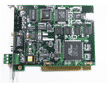
3.0 DLPCI-Hardware Layout
This Section contains information of the physical position and purpose of the components of the DLPCI.
- At the top of the bracket has Configure push button switch.
- The LED’s are from top STATUS LED (ERR), NETWORK LED ( CHA) and BUS LED (CHB).
- 9 Pin DSUB connector (External Serial RS232 communication port for DLPCI configuration, used in case there is a bus communication issue).
- CHA DH+ or DH-485 3 pin Screw terminal (Phoenix Type) pin 1 is the bottom one.
- PCI Bus connector (CHB the DF1 Physical communication port).
4.0 Mode of Operation
4.1 Online Mode of Operation
Online Mode is the normal operating Mode of the DLPCI. In this mode the Channels are now
configured as they are defined by the configuration and the DLPCI Model. The DLPCI is ready to
interface your equipment.
4.2 Offline Mode
Once the Configure Pushbutton is pressed the Offline BIOS Manager is started. Using either the
configuration software and the “DL Offline Manager” option or a Windows Hyper Terminal type
program with com port settings of 19,2KBaud,8,N,1 and Xon/Xoff flow control..
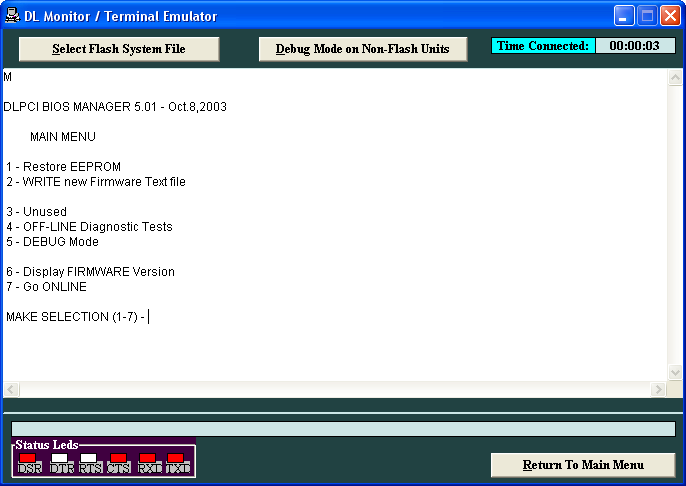
DLPCI BIOS MANAGER 5.01 - Oct.8.2003
MAIN MENU
1 - Restore EEPROM
2 - WRITE new Firmware Text file
3 - Unused
4 - OFF-LINE Diagnostics
5 - DEBUG Mode
6 - Display FIRMWARE Version
7 – Go ONLINE
MAKE SELECTION (1-7) -
DLPCI BIOS MANAGER 5.01 - Oct.8.2003
MAIN MENU
1 - Restore EEPROM
2 - WRITE new Firmware Text file
3 - Unused
4 - OFF-LINE Diagnostics
5 - DEBUG Mode
6 - Display FIRMWARE Version
7 – Go ONLINE
MAKE SELECTION (1-7) -
4.3 BIOS Manager Options
1. Restore EEPROM to factory settings
Once pressed you will be asked “Restore EEPROM to defaults (Y/N)?” If the answer
is “Y”es then the Online parameters will be reset to defaults of Address 1, and
settings of 9600,N,8,1 on the communication Channel to the COBOX.
2. Write New Firmware
Once pressed the message “This *WILL* overwrite DATALINK system code enter
(Y/N) to proceed” will be displayed. Hit “Y” and the next message will appear
telling you that it is alright to send the new firmware to the Flash;
ERASING FLASH, PLEASE WAIT...SEND FIRMWARE TEXT FILE NOW...
Once the message to send the firmware appears then either click on the “Burn Flash System File” button to select the .txt file to send, or send the Text File under HyperTerminal.
Wait for an “*A-OK* BURN COMPLETE!” message to appear.
Unused
. Off-Line Diagnostics
Starts a series of tests to test the DLPCI’s hardware and should only be done if instructed so by a trained person. Debug Mode
Starts up a DLPCI internal Debug mode that can be used by trained personnel to debug problems and check
hardware configuration and operation. Firmware Version
Once selected the current DLPCI model and version numbers will be displayed. Can be used to check the correct
firmware was burnt into the Flash or if the DLPCI has the most up to date firmware in the Flash. Online
Does a soft “software” reset of the unit to put it online. 5.0 Switch and LED Indicator Functions
5.1 Switch Functions
The Configure pushbutton takes the DLPCI out of On-Line operation mode and puts it in the
BIOS Manager mode. The BIOS Manager mode also allows for configuration parameters to be
downloaded from or uploaded to the Windows based configuration software (DL32). When this
mode has been entered the STATUS LED will be RED and BUS LED will be Green while NET
LED will be off. To put the unit back On-line use option 7 from the BIOS menu or can power
off then on the PC.
5.2 Indicator Functions
5.2.1 Power-Up and Reset Sequence
On Power-up the DLPCI executes a self diagnostic check-up or the ram and flash firmware. The
correct LED indicator sequence to show the DLPCI is functioning properly is as follows: After
all LEDS go out.- LED
- Status
- STATUSLED
- RED for 0.5 seconds
- BUSLED
- Green for 0.5 seconds
- NETLED
- Green for 0.5 seconds
5.2.2 Normal On-line Operation
The following is a description of the normal operation of the Channel LEDs on the DLPCI.- LED
- Description of Operation
- NET LED
- Solid Green when on line on DH+ or Flashing on DH485 Network.
- BUS LED
- Flashes or solid Green if there is activity of the DF1 side.
- STATUS LED
- Flashes RED for 0.5 seconds if a NAK is received or transmitted in DF1 protocol. Will also flash RED if duplicate node address on DH+/DH485 exists.
5.2.3 On-Line, Power-Up and Reset Errors
The following table describes the meaning of LED patterns if the internal diagnostic tests detect
an error on Reset/Power-Up.- LED Pattern
- Description of Problem
- All Three
LED’s
Flashing - The flash has not be burnt properly and the A-OK was not transmitted. Please reburn the flash with the correct text file. Contact Customer Support for help.
- Start-up
Sequence
keeps
repeating. - The BIOS has been corrupted. A new Flash Chip has to be supplied by the factory. Please contact Customer support.
- Start-up
Sequence keeps
repeating - The DLPCI EEPROM is corrupt. Please Restore to Factory settings (See Section 1.1) and then reconfigure the unit.
5.2.4 Off-Line Modes
The following table describes the meaning of LED patterns in the different Off-Line modes of
operation.- LED Pattern
- Description of Problem
- STATUSLED ON
NETLED OFF
and BUSLED ON - BIOS Manager/Configuration Parameter Download/Upload
- All Three
LED’s ON - Offline Debug Mode
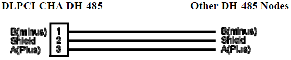
6.0 DLPCI Wiring Diagrams
6.1 Online Cable DLPCI-CHA DH+
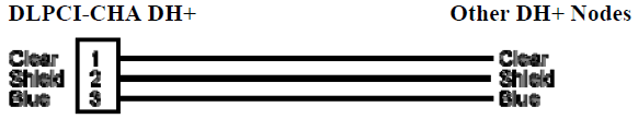
Note: Clear & Blue might have to be swapped depending on existing DH+ wiring
6.2 RS-232 Null Modem Cable
7.0 DLPCI DH-485/DH+ Networking Applications
7.1 DLPCI-DF1 – DF1 to DH-485/DH+ interface
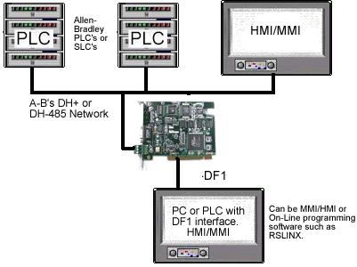
Note : PC can be running RS-LINX or like software (MMI) to have access to nodes
on the DH-485/DH+ Network.
on the DH-485/DH+ Network.
Appendix A : Installing the RS232 Serial Driver For the DLPCI
A1: DLPCI Windows XP 32 bit driver installation
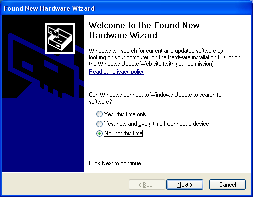
After installing the card in any PCI bus when you power up the PC it will come up with Found new hard
ware wizard as shown, select No, not this time as shown.
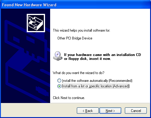
Then select Install from a list or specific location.
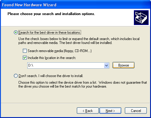
Select Don’t search, I will choose the driver to install.

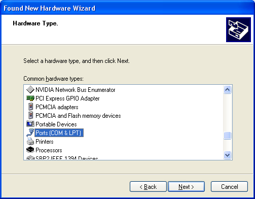
Select Ports(COM & LPT) as shown below.
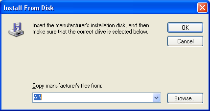
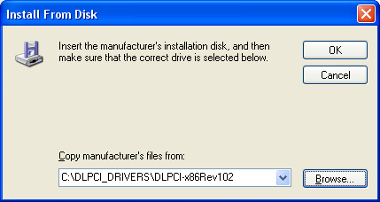
Here you click on Have a Disk.
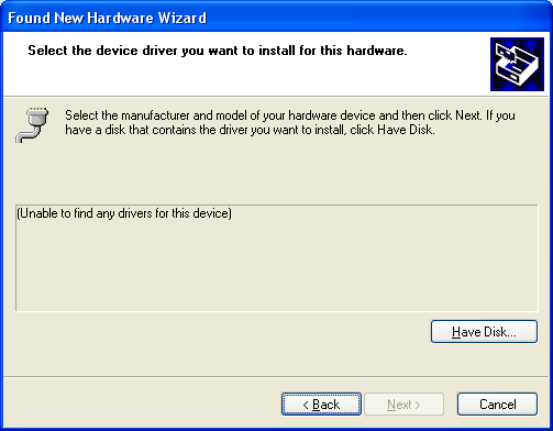
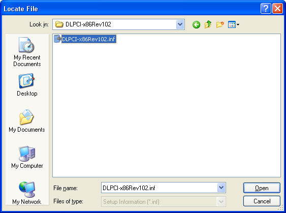
Now brows to where you have the diver saved.
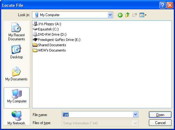
Select the latest driver as shown below.
Here click on OK
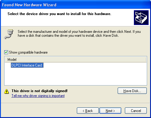
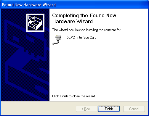
You will see under Model the DLPCI Interface Card click on it to highlight it, and then click on Next.
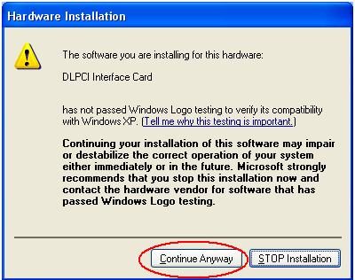
Click on Continue Anyway
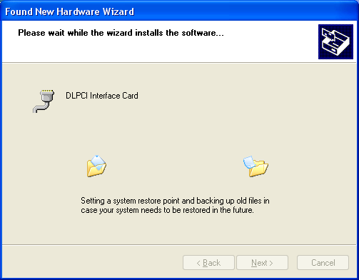
Click on finish.
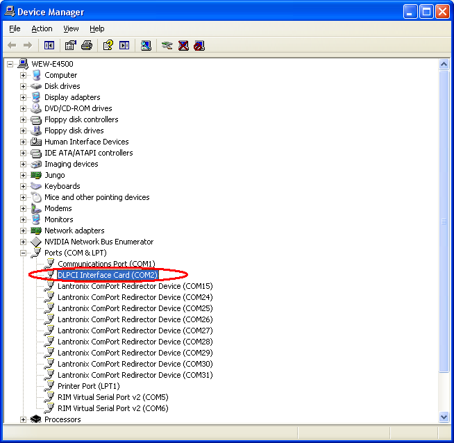
In the Device manager, check the comport number for the DLCPI and remember it to use in configuring
the Allen Bradley DF1 driver.
You can change the port number for any comport number that is available on your PC.
You can change the port number for any comport number that is available on your PC.

Close and restart your PC.
A2- Equustek DLPCI ( Allen BradleyDF1 to DH+ / DH485 ) PCI Bus Card with Windows 7
DLPCI Windows 7 32 bit driver installation.
If windows set to automatic windows driver installation, and after the DLCPI is installed in the PC the DLPCI driver installation will fail, so you need to go to device manager, you will find the failed device with yellow exclamation mark (Other PCI Bridge) as shown below.
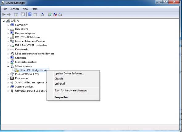
Right click on Other PCI bridge device and click on update driver, then click on Browse my computer
for driver software.
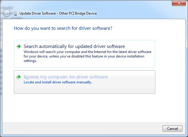
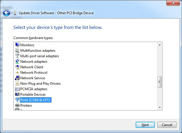
It will come up with the windows shown below scroll down, select Ports(COM & LPT) and click Next.
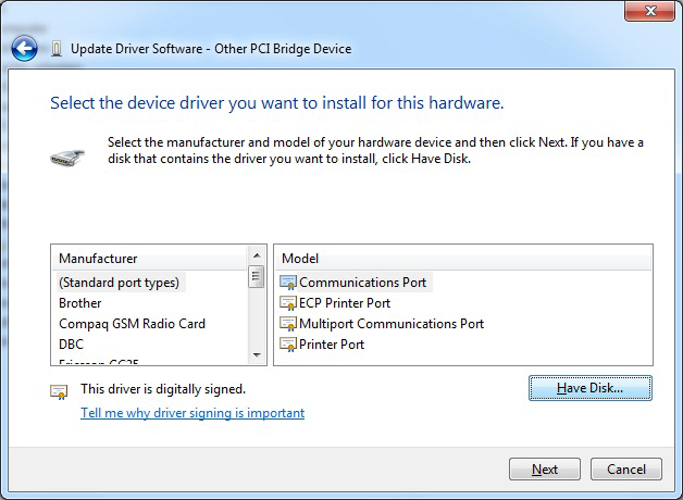
From the window shown below make sure (Standard port Types) and (Communications Port) are
selected and then click on Have Disk.
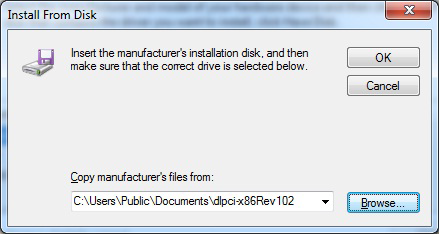
It will come up with a window where you can browse to the location of the driver file saved on your
hard drive or CD.
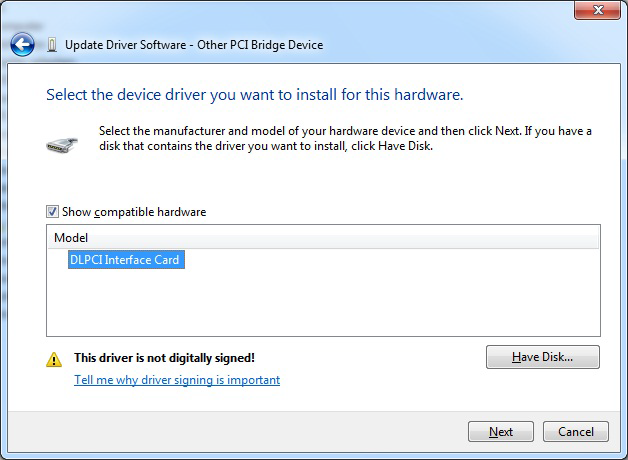
Here it will show the DLPCI Interface card highlight it, and click Next.
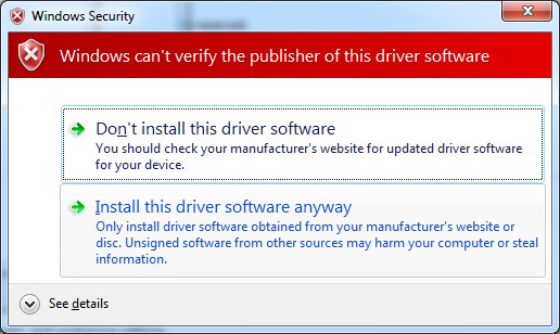
To continue installing the driver, click on Install this driver software anyway.
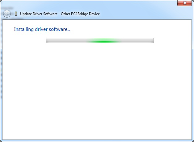
Wait for the driver to complete installation.
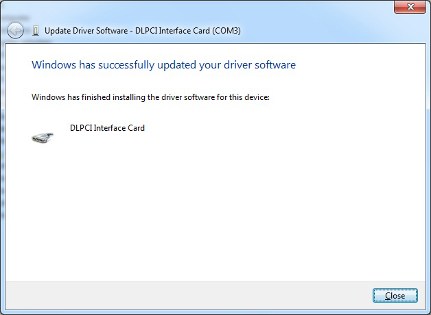
Here you will see the successfully completed message click on Close.
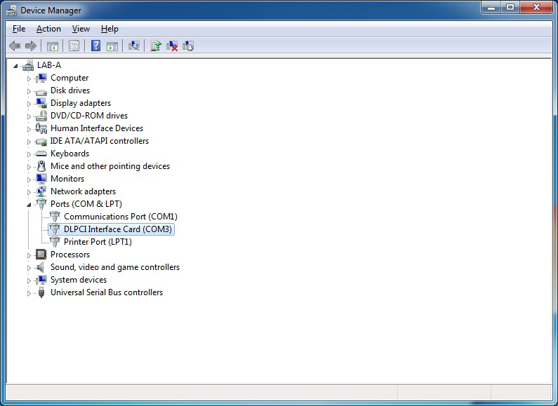
Go back to your Device Manager under Ports ( COM & LPT) you should see the DLPCI Interface card
with specific COM port number that you will use with your Allen Bradley DF1 driver.
Now you can restart your PC and if you encounter any issue just shut down the PC and move the DLCPI
to another PCI slot it will resolve that issue if any exists.
That will complete the installation of the WIN7 PCI driver for the card.
Again please note this serial port number is used for setting up the DF1 drive, later on.
Again please note this serial port number is used for setting up the DF1 drive, later on.
Appendix B : DLPCI Configuration:
To configure the DLPCI you need the DL32 configuration software installed. Insert the Equustek CD.
The selection screen should start up automatically. If it does not start automatically, select Run from the
Start Menu and enter “D:\Autorun.exe” where “D” is the drive letter of your CD drive.

From the selection screen, choose Install Software → Install DL32 Configuration Software → Install
Latest DL32 Software to install the latest version of DL32.
To run the DL32 software, Press the Start Button (bottom left of screen) then select Programs → Equustek Solutions Inc. → DL32.
Before Starting the DL32 Configuration Software, find out what COM port has been assigned to the DLPCI. To do this, open the Device Manager (from the Control Panel, select System, then on the Hardware tab in the System Properties window, select Device Manager). Under Ports (COM & LPT) you will see the COM port assigned to the DLPCI.
Start the DL32
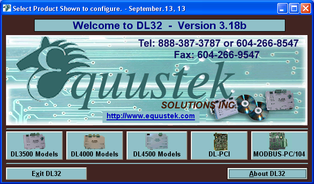
From the DL32 Welcome Screen, click on the DL-PCI button.
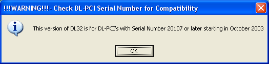
Ensure the SERIAL NUMBER of your DLPCI is greater than 20107, if not then you need to use the
older DL32 Version 2.03 (can be downloaded from our Equustek website under download).
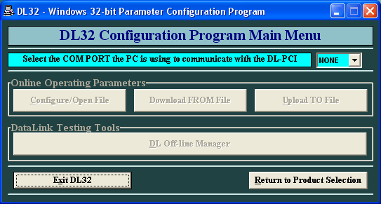
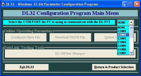
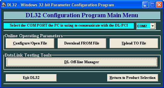
From the DL32 Main Menu, select the COM Port that has been assigned to the DLPCI.
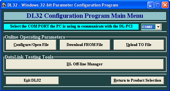
Click on DL Offline manager
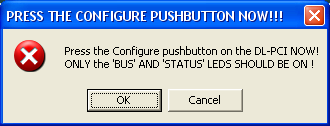
Click on ok after you press the configure pushbutton on the DLPCI card.
Here just hit the enter key to make sure you have are communicating with the card and you can see the
menu as shown below.
Click on return to main menu, and then click the Configure/Open File button.
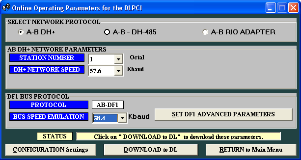
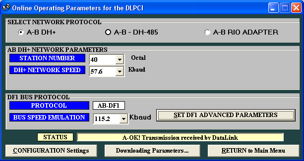
Select the Network Protocol (based on the model of DLPCI you have ordered). DH+ or DH485.
In AB network parameters select the card Data highway node address number, and your Data Highway
network baud rate.
As for DF1 set the emulated serial bus speed and click on Set DF1 Advanced Parameters.
As for DF1 set the emulated serial bus speed and click on Set DF1 Advanced Parameters.
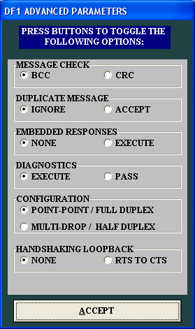
Here select parameters shown below for Advanced DF1 protocol settings. Typical users will want to
leave the settings at their default values.
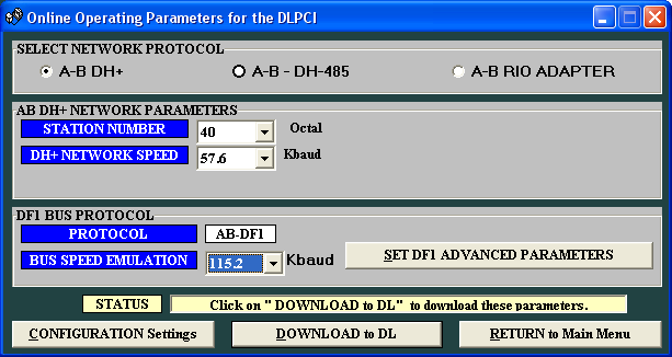
In an example here we set the node address to 40 octal and DH+ 57.6KBuad and 115.2K baud serial
DF1 speed, after setting all the parameters click on download to DL
Press the pushbutton switch on the card if you have not done that yet and click on ok.

Wait until you see A OK transmission received by DataLink as shown below.
This completes the DLPCI card configuration, close the program and restart the PC to set your DF1
driver.