EQ-DCM
User Manual
PDF Download
www.equustek.com
Revision 1.02 – Sep 10, 2013
Contents
POWER-UP SEQUENCE
9
ONLINE LED OPERATION
9
OFFLINE LED OPERATION
10
LED ERROR SEQUENCES
10
11
INSTALLING THE EQ-DCM
11
OVERVIEW
12
INSTALLING THE SOFTWARE
12
STARTING THE SOFTWARE
12
CONFIGURE
13
UPGRADE FIRMWARE
14
DEVICE INFORMATION
ERROR! BOOKMARK NOT DEFINED.
OFFLINE MANAGER
14
CONFIGURING THE EQ-DCM
15
OPEN A SAVED CONFIGURATION
15
SERIAL COMMUNICATION SETTINGS
15
Baud Rate
16
Data Bits
16
Stop Bits
16
Parity
16
Handshaking
16
ETHERNET COMMUNICATION SETTINGS
16
DHCP
17
IP Address
17
Subnet Mask
17
Default Gateway
17
Speed
17
Socket Timeout
17
SERIAL PROTOCOL SETTINGS
17
Allan-Bradley DF1
18
Communication Mode
18
Error Detection
18
ASCII
18
ETHERNET PROTOCOL SETTINGS
18
AB Ethernet
19
ROUTING TABLE SETUP
19
Add Route
19
Source Port
20
Destination Address Range
20
Destination Port
20
IP Address
20
Edit Route
20
Delete Route
20
Clear Routing Table
20
PROTOCOL CONVERSION SETTINGS
21
ASCII – DF1
21
File Number
21
Element Number
21
File Type
21
Message Function
21
DOWNLOADING AND SAVING SETTINGS
22
UPGRADING FIRMWARE IN THE EQ-DCM
23
OVERVIEW
25
RESTORE EEPROM TO FACTORY DEFAULTS
25
WRITE NEW FIRMWARE
26
MEMORY DUMP
27
DIAGNOSTICS
27
DEBUG
27
SHOW FIRMWARE VERSION
27
GO ONLINE
27
28
RS-232 CONNECTION
28
No Handshaking
28
RTS/CTS Handshaking
28
RS-422 CONNECTION
29
RS-485 CONNECTION
29
ETHERNET CONNECTION
30
Straight Through Cable
30
Cross Over Cable
30
AB ETHERNET TO DF1
31
Introduction
About This Manual
This manual is designed to assist with installation and configuration of the EQDCM gateway device. It is recommended that this manual be read before configuring the EQ-DCM gateway device.
Intended Audience
This manual is intended for the person responsible for installing and configuring the EQ-DCM gateway. It is assumed that the person configuring the device is familiar with the protocols they will be working with and has experience configuring network devices.
Hardware Specifications
Physical Specifications
Dimensions :
1.2” H x 4.75” D x 3.2” W (30.4 x 120.7 x 81.3 mm)
Weight :
0.56 lbs (0.2 kg)
Installation :
Metal Enclosure; Desktop, #8 Bolts, or Din Rail
Operating Environment :
32 to 122°F (0to 50°C)
Storage :
-40 to 185°F (-40 to 85°C)
Humidity :
5% to 95% non-condensing
Power :
9 – 27 Volts DC, 1.8 Watts
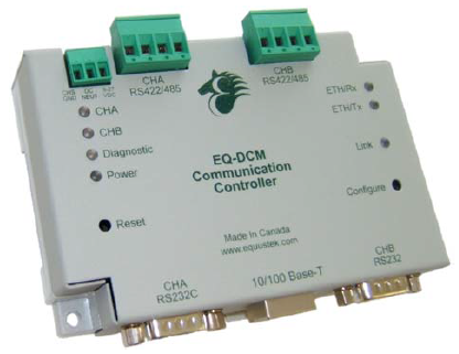
Hardware Layout
The EQ-DCM gateway consists of the following hardware components :
- Power Supply
- Two RS-232, RS-422, or RS-485 serial communications ports
- 10/100BaseT Ethernet Port
- Two pushbuttons (Reset and Configure)
- Seven LED’s
Operating Specifications
The following section describes the operation of the EQ-DCM hardware.
Channel A (CHA)
Channel A is a serial communications port, capable of RS-232, RS-422 and RS-485 wire modes. Channel A can communicate with both the Ethernet port and Channel B. This channel can be configured for the following communication settings:
• Speeds : 2400, 9600, 19200, 38400, 57600, or 115200 Baud
• Data Bits : 7 or 8
• Parity : None, Even, or Odd
• Stop Bits : 1 or 2
• Handshaking : None or RTS/CTS flow control
This channel currently supports the serial MODBUS, DF1 Full Duplex and ASCII protocols.
Channel B (CHB)
Channel B is a serial communications port, capable of RS-232, RS-422 and RS-485 wire modes. Channel B can communicate with both the Ethernet port and Channel A. This channel can be configured for the following communication settings:
• Speeds : 2400, 9600, 19200, 38400, 57600, or 115200 Baud
• Data Bits : 7 or 8
• Parity : None, Even, or Odd
• Stop Bits : 1 or 2
• Handshaking : None
This channel currently supports the DF1 Full Duplex protocol and ASCII protocol. Other protocols will be available in the future.
Ethernet 10/100BaseT
The Ethernet port can be capable of speeds of 10 or 100 Mbits/sec and uses twisted pair cables for connecting to the RJ45 port. The Ethernet port
is capable of communicating with both Channel A and Channel B.
This channel currently supports the AB Ethernet protocol. Other protocols will be available in the future.
The EQ-DCM is limited to a maximum of 15 simultaneous TCP connections.
This channel currently supports the AB Ethernet protocol. Other protocols will be available in the future.
The EQ-DCM is limited to a maximum of 15 simultaneous TCP connections.
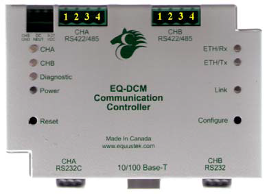
LED’s
The EQ-DCM has seven LED’s located on the top of the device. Four LED’s on the left and three LED’s on the right. Below is a list of the LED’s.
Left Side LED’s
Right Side LED’s
Left Side LED’s
• CHA
• CHB
• Diagnostic
• Power
Right Side LED’s
• ETH/Rx
• ETH/Tx
• Link
Pushbuttons
The EQ-DCM has two pushbuttons: Reset and Configure. The description of each is located below.
• Reset : The reset button is located on the left side of the EQ-DCM and is used to perform a hardware reset.
• Configure : The configure button is located on the right side of the EQ-DCM and is used to put the EQ-DCM into its Offline operating mode.
LED Operation
Power-Up Sequence
When the EQ-DCM powers up, it performs a self diagnostic check to ensure that everything is working properly. During power-up, the LED’s will blink in a specific sequence and then start its online operation. Below is the LED power-up sequence.
After the power-up sequence has completed the EQ-DCM will be online.
CHA : Green
↓
CHB : Green
↓
Diagnostic : Green
↓
CHA, CHB, Diagnostic: Green
After the power-up sequence has completed the EQ-DCM will be online.
Online LED Operation
When the EQ-DCM is in its online operation, the LED’s will perform as shown in the table below.
| LED | Description |
|---|---|
| CHA : Green | CHA is transmitting and/or receiving data packets. |
| CHA : Red | CHA received a bad data packet or transmitted a NAK. |
| CHB : Green | CHB is transmitting and/or receiving data packets. |
| CHB : Red | CHB received a bad data packet or transmitted a NAK. |
| Diagnostic : Off | The diagnostic led should never be on in online operation unless a hardware error has occurred. |
| ETH/Rx : Green | Blinks when data packets are received. |
| ETH/Tx : Green | Blinks when data packets are transmitted. |
| Link : Green | Ethernet port is connected |
| Link : Off | Ethernet port is not connected. |
Offline LED Operation
When the Configure button on the EQ-DCM is pressed, the device is put into its offline mode. For more information about the offline mode, see the chapter regarding the Offline Manager. The following table shows the possible LED sequences for offline operation.
| LED Sequence | Description |
|---|---|
| CHA and CHB: Red Diagnostic GREEN |
Configure Mode. |
| CHA, CHB, and Diagnostic : Green | Debug mode |
LED Error Sequences
When the EQ-DCM self diagnostic check encounters a problem, the LED’s will blink in a particular sequence depending on the error that occurred. Below is a table that outlines the possible errors and their LED sequence.
| LED Sequence | Error | Description |
|---|---|---|
| Diagnostic: Solid Red CHA and CHB: Blinks Green 1x |
Data Bus | An error has occurred with the data bus. Contact technical support for assistance. |
| Diagnostic: Solid Red CHA and CHB: Blinks Green 2x |
Address Bus | CHA received a bad data packet or transmitted a NAK. |
| Diagnostic: Solid Red CHA and CHB: Blinks Green 3x |
RAM | A problem has occurred with the RAM and will need to be replaced. Contact technical support for assistance. |
| Diagnostic : Solid Red CHA and CHB: Blinks Green 4x |
UART | A problem has occurred with one of the UART’s Tx, Rx, CTS, or RTS lines. Contact technical support for assistance. |
| Diagnostic, CHA, and CHB: Blinks Green and Red |
Firmware | The model of EQ-DCM does not support the installed firmware.Contact technical support to obtain the correct firmware. |
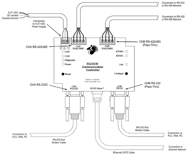
Installation
Installing the EQ-DCM
The diagram below shows the connections for installing the EQ-DCM. Note that it is not possible to have both the RS-232 and RS-422/485 connected at the same time for CHA and CHB.
EQ32 Software
Overview
The EQ32 Configuration Software is used to configure the EQ-DCM online operating parameters and upgrade the firmware. The software can also be used to view the serial number, model number, hardware number, and version of firmware in the EQ-DCM. The following section explains how to use the EQ32 Configuration Software with the EQ-DCM gateway.
Installing the Software
The EQ32 Configuration Software must be installed on a PC before using the software.
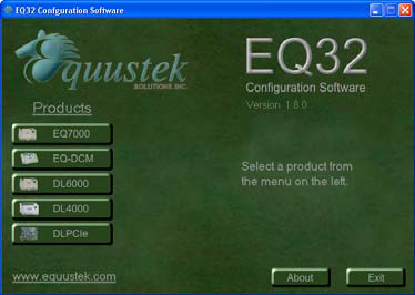
Starting the Software
The EQ32 Configuration Software is located by default under the Programs Menu in the Equustek Solutions Inc. folder.
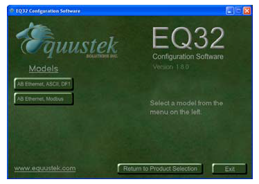
Once the program has been started, the Product Selection screen will appear. From this screen, select the product that you wish to configure or upgrade.
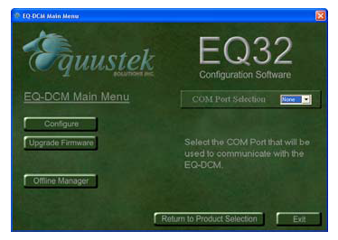
 After Selecting the EQ-DCM from the product menu, the EQ-DCM Main Menu will appear.
 From this menu choose the right protocol you have ASCII/DF1 or MODBUS.
From this screen, choose one of the three options available.
Start → Programs → Equustek Solutions Inc. → EQ32
Once the program has been started, the Product Selection screen will appear. From this screen, select the product that you wish to configure or upgrade.
From this screen, choose one of the three options available.
- Configure
- Upgrade Firmware
- Offline Manager
Configure
The Configure option is used to configure the online operating parameters of the EQ-DCM. These options include serial parameters, protocol parameters, IP address, and routing tables. For more information about configuring the EQDCM, see the chapter dedicated to configuring the EQ-DCM.
Upgrade Firmware
The Upgrade Firmware option is used to install firmware to the EQ-DCM. When new firmware upgrades are available, use this option to install the firmware. For more information about upgrading the firmware in the EQ-DCM, see the chapter dedicated to upgrading the firmware in the EQ-DCM.

Offline Manager
The Offline Manager option is used to access the OFFLINE Manager and offline options available on the EQ-DCM. The OFFLINE Manager for the EQ-DCM can also be accessed by opening a Hyper Terminal window with the following communication settings.
 For more information regarding the EQ-DCM Offline Manager, see the chapter dedicated to the Offline Manager.
- Bits Per Second : 38400 bps
- Data Bits : 8
- Stop Bits : 1
- Parity : None
- Handshaking : Xon/Xoff
Configuration
Configuring the EQ-DCM
Before using the EQ-DCM, the online operating parameters must be configured. These parameters include serial parameters, protocols and protocol parameters, Ethernet parameters (such as IP address), and routing tables. Use the EQ32Configuration Software to configure the EQ-DCM. The following sections explain the available options.
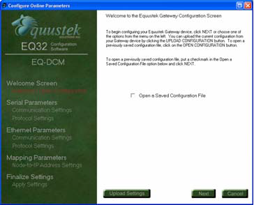
Open a Saved Configuration
When the Configure option is selected from the EQ32 main menu, the first screen will give the option to open a saved configuration file. To open a saved
configuration file, put a check beside the Open a Saved Configuration File option.

The current configuration that is stored in the EQ-DCM can be uploaded by pressing the configure button on the EQ-DCM and
then clicking the Upload Settings button.
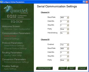
Serial Communication Settings
The Serial Communication Settings are used to setup CHA and CHB serial parameters for communicating with a PLC, HMI, or other serial devices. The available options are listed and explained below.
- Baud Rate
- Data Bits
- Stop Bits
- Parity
- Handshaking
Baud Rate
CHA and CHB can be configured for the following baud rates: 2400, 4800, 9600, 19200, 38400, 57600, and 115200 bps. The default setting is 9600 bps.
Data Bits
CHA and CHB can be configured for either 7 or 8 data bits. The default setting is 8 data bits. Stop Bits
CHA and CHB can be configured for either 1 or 2 stop bits. The default setting is 1 stop bit.
Parity
CHA and CHB can be configured for even parity, odd parity, or no parity. The default setting is no parity.
Handshaking
CHA can be configured to use RTS/CTS handshaking or no handshaking. CHB can only be configured for no handshaking. The default setting is no handshaking.Ethernet Communication Settings
The Ethernet Communication Settings is where the IP address, subnet mask, and default gateway are configured. Below is a list of settings that can be adjusted.
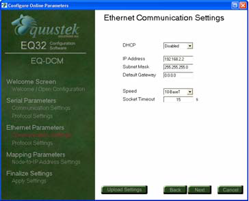
- DHCP
- IP Address
- Subnet Mask
- Default Gateway
- Speed
- Socket Timeout
DHCP
The DHCP option can be used to have the DHCP server automatically assign an IP address to the EQ-DCM.
IP Address
The IP address is used to identify the EQ-DCM on the network. The default IP address is 192.168.2.2.
Subnet Mask
The subnet mask is used to separate the network address from host address. The default subnet mask is 255.255.255.0.
Default Gateway
Default Gateway The default gateway is the IP address of the gateway that connects the local area network to the internet. This value can be left blank. The default value for the gateway is 192.168.2.1.
Speed
The EQ-DCM can be configured to have the Ethernet connection operate at 10 Mbits/s or 100 MBits/s. The default setting is 10 MBits/s.
Socket Timeout
The socket Timeout is the length of time a socket will remain open while there is no activity. The default value is 30 seconds.
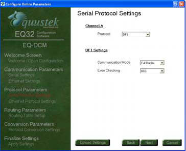
Serial Protocol Settings
The EQ-DCM in this model supports Allan-Bradley’s DF1 protocol and the ASCII protocol. After choosing the protocol, the available options for that protocol will be displayed.
Currently available serial protocols are isted below.
Currently available serial protocols are isted below.
- Allan-Bradley DF1
- ASCII
- MODBUS
Allan-Bradley DF1
The DF1 protocol is a serial protocol developed by Allan-Bradley for communicating with PLC’s, HMI’s, and other DF1 capable devices. The currently available options are as follows :
Communication Mode
Currently only the Full Duplex mode is available. The Half duplex mode will be available in the near future.
Error Detection
There are two methods of error detection available for the DF1 protocol, BCC and CRC error checking.
ASCII
The ASCII protocol is a serial protocol used to communicate with scanners, printers, and other ASCII devices. There is no protocol setup needed for the
ASCII protocol. The EQ-DCM will continue to receive data until a carriage return is received.
MODBUS
Please refer to MODBUS application note for details.
Ethernet Protocol Settings
Currently only Allan-Bradley’s AB Ethernet protocol is available. After choosing the protocol, the available options for that protocol will be displayed.
Currently available protocols are listed below.
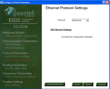
Currently available protocols are listed below.
- AB Ethernet
AB Ethernet
AB Ethernet (or CSP as it is referred to by Allan-Bradley) is an Ethernet protocol developed by Allan-Bradley for communicating with PLC’s, HMI’s, and other AB Ethernet capable devices. There is currently no protocol setup needed for the AB Ethernet protocol.
Routing Table Setup
The routing table is a feature used by the EQ-DCM to determine where incoming message requests are to be routed. Messages can be routed to either of the serial ports or to the Ethernet port. When the EQ-DCM searches through its routing table, it will use the first table entry that matches the criteria in the incoming message. Because of this, the order in which the data is entered is important. The routing table can support up to a maximum of 20 routes.
To define a route in the table, the following information is needs to be entered.
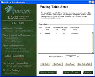
To define a route in the table, the following information is needs to be entered.
- Source Port
- Destination Address Range
- Destination Port
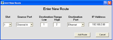
Add Route
The Add Route button is used to create a new route in the routing table. When adding new routes, the slot number automatically defaults to the next available slot in the routing table. If multiple routes are present, the slot number can be changed to insert a new route between existing entries.
Source Port
The source port is the port where incoming message requests will be received.
Destination Address Range
The destination address range is used to determine where messages need to be routed. The address range can be a singe value or a range of values. In order to select a single address, enter the same value for both the low and high addresses. Any messages that fall into the defined range will be routed to the appropriate destination port. Messages that are received and do not fall within the defined range are discarded.
When messages are received from the Ethernet port, the remote destination value is examined to see if the message falls within the defined range in the routing table.
The allowed values for the destination range are 0 to 255.
When messages are received from the Ethernet port, the remote destination value is examined to see if the message falls within the defined range in the routing table.
The allowed values for the destination range are 0 to 255.
Destination Port
The destination port is the port that messages will be routed to if they meet the criteria defined in the routing table.
IP Address
The IP address is only used if the Ethernet port is entered as the destination port. The IP address is the address of the Ethernet device that messages will be sent to.
Edit Route
The Edit Route button is used to edit an existing route. When the slot of the route to be edited is selected, the information about that entry is displayed and can be changed.
Delete Route
The Delete Route button is used to remove a single entry from the table.
Clear Routing Table
The Clear Routing Table button is used to remove all of the entries from the routing table.
Protocol Conversion Settings
When communicating to devices that use different protocols, it is sometimes necessary to setup protocol conversion parameters. These conversion parameters
are in addition to the protocol setup of each port. Below is an explanation of conversion parameters for converting between certain protocols.
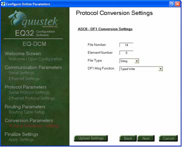
ASCII – DF1
When converting between ASCII and DF1, the following conversion parameters are needed for proper communication. When data is received from the port that is configured for the ASCII protocol, the low address defined in the destination address range of the routing table will be used as the destination byte when
formatting the DF1 message. The following are the conversion parameters required for converting between ASCII and DF1.
- File Number
- Element Number
- File Type
- Message Function
File Number
This is the file number that ASCII data will be sent to.
Element Number
This is the element number for the specified file number that ASCII data will be sent to.
File Type
The file type identifies the type of data file that ASCII data will be sent to. The available file types are listed below.
- Integer
- String
Message Function
The message function defines the type of DF1 message that will be formatted. The available functions are listed below.
- Typed Write
- Protected Typed Logical Write
Downloading and Saving Settings
After the settings have been configured, the last step is to download or save them. The three options available are listed below.
- Download Configuration
- Download and Save Configuration
- Save Configuration
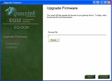
Upgrading Firmware
Upgrading Firmware in the EQ-DCM
When new firmware updates are available for the EQ-DCM, the firmware can be installed by using the Upgrade Firmware Option from the main menu in the EQ32 Configuration software. The following steps show how to upgrade the firmware in the EQ-DCM. If you encounter any issue then please use other way explained in Application notes.
1. After choosing the Upgrade Firmware option from the main menu, you will be prompted for the firmware file (the firmware file will have a .rom extension). Choose the firmware file by clicking the Browse button or entering the path of the file. Click Next to continue.
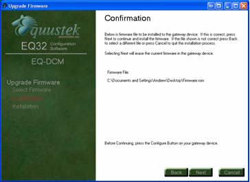
2. The next screen will ask you to confirm the file that has been chosen. If the file chosen is correct, click Next to start the installation process.
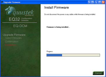
3. While the firmware is being installed, a progress bar will show how far along the installation is.
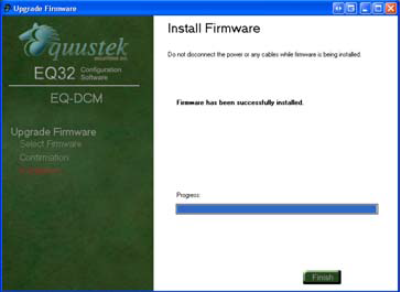
4. After the firmware has been downloaded and installed, a message will appear showing the status of the upgrade.
Offline Manager
Overview
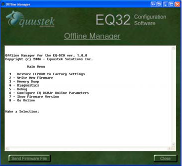
The Offline Manager is an offline utility program that is started when the Configure button on the EQ DCM is pressed. This utility program allows a user access to the offline options for the EQ DCM such as upgrading firmware and running offline diagnostics. The list of available options is listed below.
The OFFLINE Manager can be accessed by using the Offline Manager in the EQ32 Configuration Software or by starting a hyper terminal session in Windows. If the hyper terminal is going to be used, then configure the port settings as shown below.
1. Restore EEPROM to factory defaults
2. Write New Firmware
3. Memory Dump
4. Diagnostics
5. Debug
6. Show Firmware
7. Go Online
The OFFLINE Manager can be accessed by using the Offline Manager in the EQ32 Configuration Software or by starting a hyper terminal session in Windows. If the hyper terminal is going to be used, then configure the port settings as shown below.
- Bits per second: 38400 bps
- Data Bits : 8
- Parity: : None
- Stop Bits : 1
- Flow Control : Xon/Xoff
Restore EEPROM to Factory Defaults
The Restore EEPROM to Factory Defaults option will erase all the parameters that were configured using the EQ32 Configuration Software and return them to the factory default settings. The factory defaults for EQ DCM are as follows. Note that these defaults may be different depending on the version of BIOS that is currently installed in your gateway device.
Note: Handshaking is only available for CHA
CHA and CHB serial Settings
- Baud Rate : 9600 bps
- Data Bits : 8
- Parity : None
- Stop Bits : 1
- Handshaking : None
Note: Handshaking is only available for CHA
Serial Protocol Settings
- Protocol : DF1
- Communication Mode : Full-Duplex
- Error Checking : BCC
- CHB Enabled : Disabled
Ethernet Settings
- DHCP : Disabled
- IP Address : 192.168.2.2
- Subnet Mask : 255.255.255.0
- Gateway : 0.0.0.0
- Speed : 10 MBits/s
- Socket Timeout : 15 seconds
Ethernet Protocol Settings
- Protocol : AB Ethernet
- Message Timeout : 6000 ms
All units are shipped with the factory default settings.
Write New Firmware
The Write New Firmware option is used to upgrade the firmware in the EQ DCM. When new firmware upgrades become available, use this option to install the firmware. After selecting this option, the user will be notified by the following message.
Press Y to proceed with the upgrade and erase the current system code. The Offline Manager will then erase the Flash Memory and ask for the new firmware file.
After installing the firmware, the following message will appear to alert the user that the firmware has been successfully installed.
If a problem occurs while installing the firmware, the following message will appear.
If the firmware fails to install, repeat the process mentioned above. If the problem persists, then contact technical support for help.
This will erase the system code. Do you want to proceed (Y/N)?
Press Y to proceed with the upgrade and erase the current system code. The Offline Manager will then erase the Flash Memory and ask for the new firmware file.
Erasing Flash
Send flash file now
After installing the firmware, the following message will appear to alert the user that the firmware has been successfully installed.
*** Flash Burn Successful ***
If a problem occurs while installing the firmware, the following message will appear.
*** ERROR ***
Flash Burn Failed
Flash Burn Failed
If the firmware fails to install, repeat the process mentioned above. If the problem persists, then contact technical support for help.
Memory Dump
The Memory Dump option is used to display the contents of the data stored in the memory of the EQ DCM. This option should only be used by trained individuals or if instructed to by technical support staff at Equustek Solutions, Inc.
Diagnostics
The Diagnostics option runs a series of tests to ensure the proper operation of the EQ DCM hardware. Below is a list of the diagnostics that are performed.
The Diagnostics should only be run by a trained individual or if instructed to by technical support staff at Equustek Solutions, Inc.
- Data Bus
- Address Bus
- RAM
- EEPROM
- UART
The Diagnostics should only be run by a trained individual or if instructed to by technical support staff at Equustek Solutions, Inc.
Debug
The Debug option allows direct read/write access to the EEPROM. This option is used to debug problems and check hardware configuration. The Debug option should only be used by a trained individual or if instructed to by technical support staff at Equustek Solutions, Inc.
Show Firmware Version
The Show Firmware Version option displays the current firmware information that is installed in the EQ DCM. This option can be used to check if the firmware in the EQ DCM is up to date.
Go Online
The Go Online option performs a software reset and puts the unit into its normal online operation.
Wiring
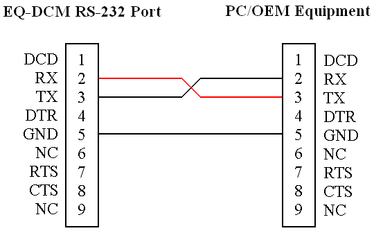
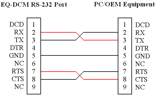
RS-232 Connection

The diagrams below show the RS-232 wiring for different configurations.
No Handshaking
Both CHA and CHB can be configured for no handshaking.
RTS/CTS Handshaking
Only CHA can be configured for RTS/CTS handshaking.
The diagram of the EQ-DCM to the Right shows the pin numbering for the RS-422 and RS-485 connections for CHA and CHB.
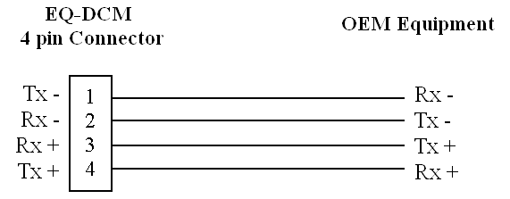
RS-422 Connection

The diagrams below show the RS-422 wiring for different configurations.
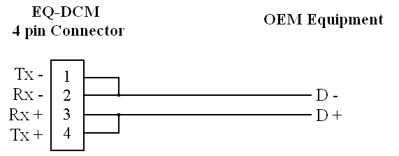
RS-485 Connection
The diagrams below show the RS-485 wiring for different configurations.
Ethernet Connection
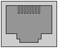
The diagrams below show the Ethernet wiring for straight through and cross over Ethernet cables. When looking at the RJ-45 jack, as shown to the left, pin 1 is the leftmost pin.
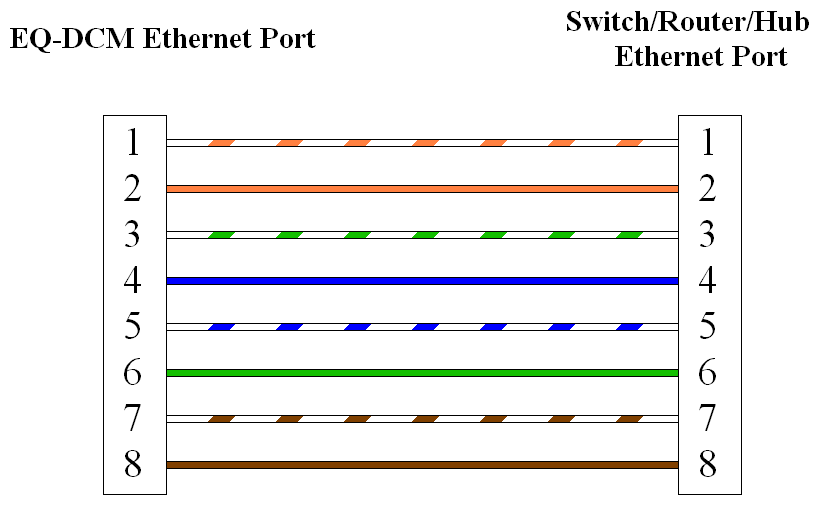
Straight Through Cable
The straight through cable is used when connecting the EQ-DCM to a switch, router, or hub.
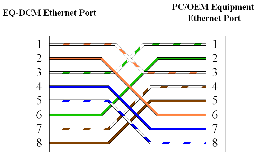
Cross Over Cable
The cross over cable is used when connecting the EQ-DCM to a PC or other equipment without going through a switch, router, or hub.
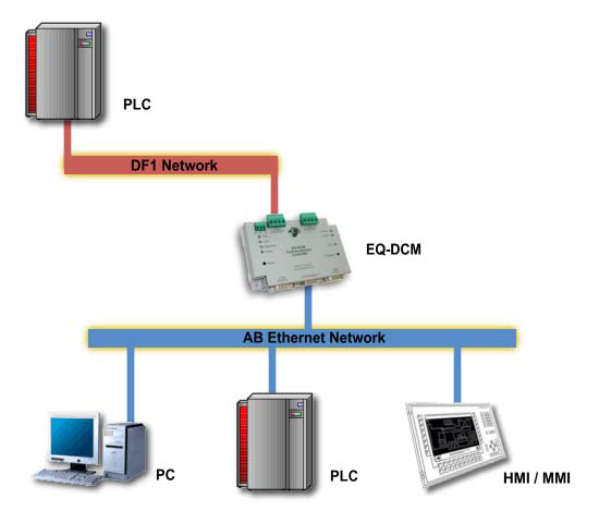
Typical Applications
AB Ethernet to DF1 Or ASCII