EQ7000
User Manual
Rev 1.04
PDF Download
www.equustek.com
Revision 1.04 – Feb 20th, 2017
Contents
INSTALLING THE EQ7000
4
OVERVIEW
8
INSTALLING THE SOFTWARE
8
STARTING THE SOFTWARE
8
CONFIGURE
9
DEVICE INFORMATION
10
OFFLINE MANAGER
10
OVERVIEW
11
OPEN A SAVED CONFIGURATION
11
DH+ OR DH485 COMMUNICATION SETTINGS
12
Node Address
12
Network Speed
12
ETHERNET COMMUNICATION SETTINGS
13
DHCP
13
IP Address
13
Subnet Mask
13
Default Gateway
13
Speed
13
Socket Timeout
14
DOWNLOADING AND SAVING SETTINGS
14
OVERVIEW
14
EZ80 OFFLINE MANAGER
15
Install New Firmware
15
Erase Flash
15
Restore EEPROM Defaults
15
Debug
15
Show Firmware Version
16
Switch Processor
16
Z182 OFFLINE MANAGER
16
Restore EEPROM
16
Write New Firmware
16
Memory Dump
16
Offline Diagnostics
17
Debug Mode
17
Firmware Version
17
Go Online
17
Switch Processor
17
OVERVIEW
20
COMMUNICATING VIA ETHERNET/IP
21
Sending Messages to DH+ devices
21
COMMUNICATING VIA AB ETHERNET
22
Sending Messages to DH+ devices
22
Browsing DH+ Network Using RSLinx
23
25
ABOUT THIS MANUAL
27
DH485 CONNECTION
27
ETHERNET CONNECTION
28
Straight Through Cable
28
Cross Over Cable
28
ETHERNET/IP AND AB ETHERNET TO DH+
28
Introduction
About This Manual
This manual is designed to assist with installation and configuration of both EQ7000 DH+ or EQ7000 DH485 gateway devices. It is recommended that this
manual be read before configuring the EQ7000 gateway device.
Intended Audience
This manual is intended for the person responsible for installing and configuring the EQ7000 gateway. It is assumed that the person configuring the device is familiar with the protocols they will be working with and has experience configuring network devices.
Hardware Specifications
Physical Specifications
Dimensions :
1.2” H x 4.75” D x 3.2” W (30.4 x 120.7 x 81.3 mm)
Weight :
0.56 lbs (0.2 kg)
Installation :
Metal Enclosure; Desktop, #8 Bolts, or Din Rail
Operating Environment :
32 to 122°F (0to 50°C)
Storage :
-40 to 185°F (-40 to 85°C)
Humidity :
5% to 95% non-condensing
Power :
9 – 27 Volts DC, 1.8 Watts
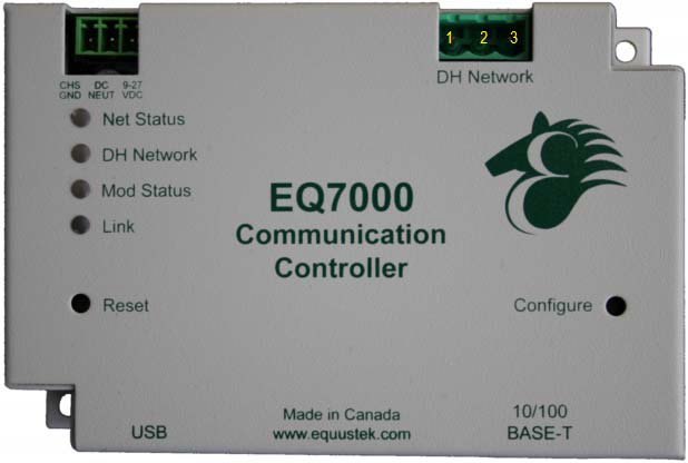
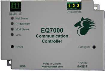
Hardware Layout
The EQ7000 gateway consists of the following hardware components :
- Power Supply
- USB port for configuration
- 10/100BaseT Ethernet Port
- Two pushbuttons (Reset and Configure)
- Four LED’s
Operating Specifications
The following section describes the operation of the EQ7000 hardware.
DH+ Network
The DHP Network port is used to connect to the DH+ network. It is capable of the following settings :
• Speeds : 57600, 115200, 230400 Baud
• Node Addresses : 0 to 77 octal
DH485 Network
The DH485 Network port is used to connect to the DH485 network. It is capable of the following settings:
• Speeds : 4800, 9600, 19200 Baud
• Node Addresses : 0 to 31 Decimal
Ethernet 10/100BaseT
The Ethernet port can be capable of speeds of 10 or 100 Mbits/sec and uses twisted pair cables for connecting to the RJ45 port. The Ethernet port
is capable of communicating with both Channel A and Channel B.
This channel currently supports AB Ethernet and Ethernet/IP. Otherprotocols will be available in the future.
This channel currently supports AB Ethernet and Ethernet/IP. Otherprotocols will be available in the future.
LED’s
The EQ7000 has four LED’s located on the top of the device on the left side. Below is a list of the LED’s. For a more detailed description of the LED’s refer to the LED Operation chapter.
• Net Status : Indicates the status of the Ethernet network
• DH Network : Indicates the status of the Data Highway Plus or DH485
network
• Mod Status : Indicates the operating status of the EQ7000
• Link : Indicates if the EQ7000 is connected to an Ethernet
Network
Pushbuttons
The EQ7000 has two pushbuttons: Reset and Configure. The description of each is located below.
• Reset : The reset button is located on the left side of the EQ7000
and is used to perform a hardware reset. Pressing the reset button does not restore factory defaults.
• Configure : The configure button is located on the right side of the
EQ7000 and is used to put the EQ7000 into its Offline operating mode.
LED Operation
Power-Up Sequence
When the EQ7000 powers up, it performs a self diagnostic check to ensure that everything is working properly. During power-up, the LED’s will blink in a specific sequence and then start its online operation. Below is the LED power-up sequence.
After the power-up sequence has completed the EQ7000 will be online.
Net Status : Green → Red → Off
↓
DH Network : Green → Red → Off
↓
Mod Status : Green → Red → Off
After the power-up sequence has completed the EQ7000 will be online.
Online LED Operation
When the EQ7000 is in its online operation, the LED’s will perform as shown in the table below.
| LED | Description |
|---|---|
| Net Status: Off | The device is not powered. |
| Net Status: Steady Green | The device has at least one established connection. |
| Net Status: Flashing Green | The device has no established connections. |
| Net Status: Flashing Red | One or more connections have timed out and have not been re-established. |
| Mod Status: Off | The device is not powered. |
| Mod Status: Steady Green | The device is operating correctly. |
| Mod Status: Flashing Green | The device is in its configuration mode. |
| Mod Status: Flashing Red | The device has detected a recoverable minor fault. |
| Mod Status: Steady Red | The device has detected a non-recoverable major fault. |
| DH Network: OFF | The device is not powered. |
| DH Network: Flashing Green | The device is not active on the DH+ network. |
| DH Network: Steady Green | The device is active on the DH+ network. |
| DH Network: Flashing Red | A duplicate node has been detected on the DH+ network. |
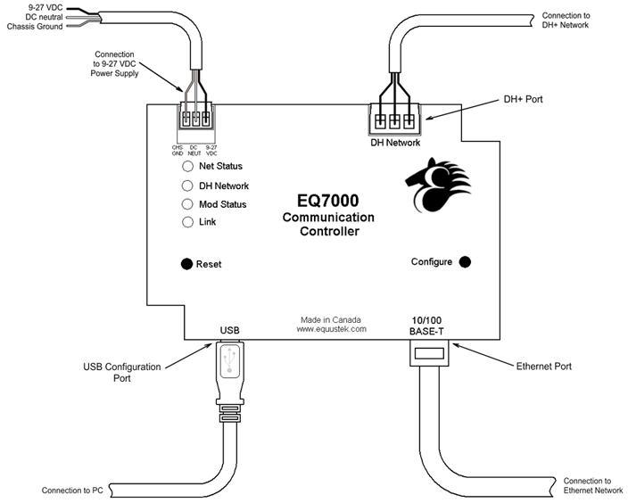
Installation
Installing the EQ7000
The diagram below shows the connections for installing the EQ7000. The USB port is used only for configuring the EQ7000 and has no effect when the unit is in its online operating mode.
EQ32 Software
Overview
The EQ32 Configuration Software is used to configure the EQ7000 online operating parameters and upgrade the firmware. The software can also be used to view the serial number, model number, hardware number, and version of firmware in the EQ7000. The following section explains how to use the EQ32 Configuration Software with the EQ7000 gateway.
Installing the Software
The EQ32 Configuration Software must be installed on a PC before using thesoftware.
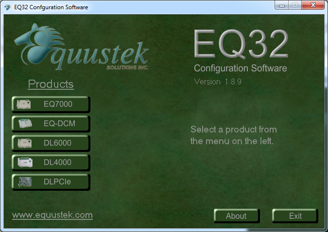
Starting the Software
The EQ32 Configuration Software is located by default under the Programs Menu in the Equustek Solutions Inc. folder.
Once the program has been started, the Product Selection screen will appear. From this screen, select the product that you wish to configure or upgrade.
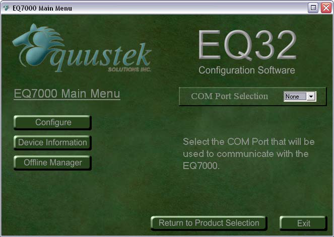
 After Selecting the EQ7000 from the product menu, the EQ7000 Main Menu will appear. From this screen, choose one of the three options available.
Start → Programs → Equustek Solutions Inc. → EQ32
Once the program has been started, the Product Selection screen will appear. From this screen, select the product that you wish to configure or upgrade.
- Configure
- Device Information
- Offline Manager
Configure
The Configure option is used to configure the online operating parameters of the EQ7000. These options include serial parameters, protocol parameters, IP address, and routing tables. For more information about configuring the EQ7000, see the chapter dedicated to configuring the EQ7000.

Device Information
The Device Information option is used to view information about the EQ7000 gateway device. The information shown here will be needed if you call for technical support. Below is a list of the information that is displayed when selecting the Device Information option.
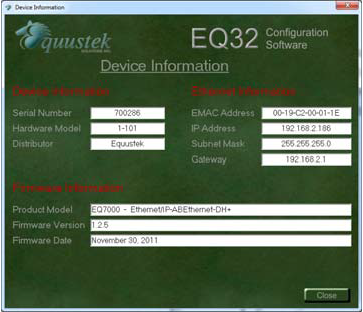
- Serial Number
- Hardware Model
- Distributor
- EMAC Address
- IP Address
- Subnet Mask
- Gateway IP Address
- Firmware Information
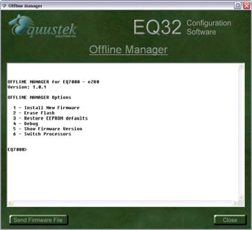
Offline Manager
The Offline Manager option is used to access the OFFLINE Manager and offline options available on the EQ7000. The OFFLINE Manager for the EQ7000 can also be accessed by opening a Hyper Terminal window with the following communication settings.
 For more information regarding the EQ7000 Offline Manager, see the chapter dedicated to the Offline Manager.
- Bits Per Second : 19200 bps
- Data Bits : 8
- Stop Bits : 1
- Parity : None
- Handshaking : Xon/Xoff
Configuration
Overview
Before using the EQ7000, the online operating parameters must be configured. These parameters include DH+ or DH485 parameters and Ethernet parameters (such as IP address). Use the EQ32 Configuration Software to configure the EQ7000. The following sections explain the available options.
Open a Saved Configuration
When the Configure option is selected from the EQ32 main menu, the first screen will give the option to open a saved configuration file. To open a saved configuration file, put a check beside the Open a Saved Configuration File option.
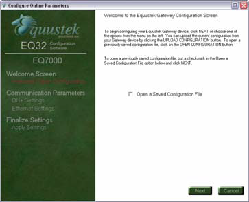
The current configuration that is stored in the EQ7000 can be uploaded by pressing the configure button on the EQ7000 and then clicking the Upload Settings button.In case no file is available click on Next.
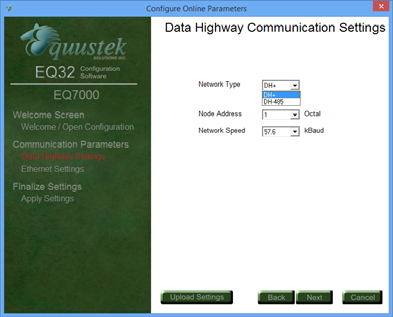
Choose Network Type DH+ or DH485
- Node Address
- Network Speed
DH+ or DH485 Communication Settings
The DH+ or DH485 Communication Settings are used to setup the DH+ or DH485 parameters of the EQ7000 so that it can communicate with other devices on the network. The available options are listed and explained below.
Node Address
The node address is used to identify the EQ7000 on the DH+ or DH845 network. This address must be unique and not in use by any other device on the DH network. The node address can be configured to any address ranging from 0 to 77 octal for DH+ Networks and 0-31 decimal for DH485 Networks. The default address is 1.
Network Speed
The network speed is the speed at which the EQ7000 will communicate with other nodes on the DH Network. The EQ7000 can be configured to communicate at 57600, 115200, and 230400 baud for DH+ , the default speed is 57600 baud or 4800, 9600, and 19200 baud for DH485.
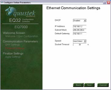
Ethernet Communication Settings
The Ethernet Communication Settings is where the IP address, subnet mask, and default gateway are configured. Below is a list of settings that can be adjusted.
- DHCP
- IP Address
- Subnet Mask
- Default Gateway
- Speed
- Socket Timeout
DHCP
The DHCP option can be used to have the DHCP server automatically assign an IP address to the EQ7000.
IP Address
The IP address is used to identify the EQ7000 on the network. The default IP address is 192.168.1.2.
Subnet Mask
The subnet mask is used to separate the network address from host address. Thedefault subnet mask is 255.255.255.0.
Default Gateway
The default gateway is the IP address of the gateway that connects the local area network to the internet. This value can be left blank. The default value for the gateway is 192.168.2.1.
Speed
The EQ7000 can be configured to have the Ethernet connection operate at 10 Mbits/s or 100 MBits/s. The default setting is 100 MBits/s.
Socket Timeout
The socket Timeout is the length of time a socket will remain open while there is no activity. The default value is 30 seconds.
Downloading and Saving Settings
After the settings have been configured, the last step is to download or save them. The three options available are listed below.
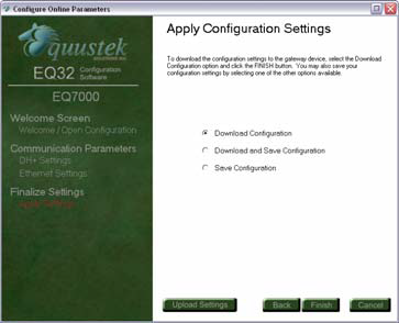
- Download Configuration
- Download and Save Configuration
- Save Configuration
If you encounter any issue downloading the configuration, just press the Reset button on the left hand side of the unit, ( or power OFF/ON) let it cycle through, then press the configure button on right hand side, then click on Finish to download the configuration file.
Offline Manager
Overview
The Offline Manager is an offline utility program that is started when the Configure button on the EQ7000 is pressed. This utility program allows a user access to the offline options for the EQ7000 such as upgrading firmware and running offline diagnostics.
The EQ7000 contains two separate processors that each has their own Offline Manager. The following sections outline the Offline Manager utility for each of the processors.
The Offline Manager can be accessed by using the Offline Manager in the EQ32 Configuration Software or by starting a hyper terminal session in Windows. If the hyper terminal is going to be used, then configure the port settings as shown below.
The Offline Manager should only be used by those who understand what they are doing or have been instructed to by a trained individual.
The EQ7000 contains two separate processors that each has their own Offline Manager. The following sections outline the Offline Manager utility for each of the processors.
The Offline Manager can be accessed by using the Offline Manager in the EQ32 Configuration Software or by starting a hyper terminal session in Windows. If the hyper terminal is going to be used, then configure the port settings as shown below.
- Bits per second: 19200 bps
- Data Bits : 8
- Parity: : None
- Stop Bits : 1
- Flow Control : Xon/Xoff
eZ80 Offline Manager
When the Configure button on the EQ7000 is pressed, the device is put into its offline mode where the following options can be accessed for the eZ80. The eZ80 Offline Manager is the default menu shown when the Configure button is pressed. The list of available options is shown below.
1. Install New Firmware
2. Erase Flash
3. Restore EEPROM defaults
4. Debug
5. Show Firmware Version
6. Switch Processor
Install New Firmware
The Install New Firmware option is used to update the firmware for the eZ80 processor in the EQ7000. The firmware is sent to the EQ7000 using the Xmodem transfer protocol. The flash memory must be erased prior to installing any new firmware. Failure to do this will result in corrupted firmware.
Erase Flash
The Erase Flash option is used to erase the flash memory for the eZ80 processor in the EQ7000. Erasing the flash must be done before installing any new firmware. Be careful as erasing the flash will erase the system code that is currently in the EQ7000.
Restore EEPROM Defaults
The Restore EEPROM Defaults EEPROM option will erase all the Ethernet settings that were configured using the EQ32 Configuration Software and return them to the factory default settings.
Ethernet Settings
DHCP: Disabled
IP Address: 192.168.1.2
Subnet Mask: 255.255.255.0
Gateway: 192.168.1.1
Speed: Auto Negotiation
Socket Timeout: 60 seconds
Debug
The Debug option allows direct read/write access to the EEPROM used by the eZ80. This option is used to debug problems and check hardware configuration.
The Debug option should only be used by a trained individual or if instructed to by technical support staff at Equustek Solutions, Inc.
Show Firmware Version
The Show Firmware Version option displays the current firmware information that is installed in the eZ80 processor of the EQ7000. This option can be used to
check if the firmware in the EQ7000 is up to date.
Switch Processor
The Switch Processor option is used to switch control to the eZ80 processor to use its offline tools.
Z182 Offline Manager
When the Configure button on the EQ7000 is pressed, the device is put into its offline mode where the following options can be accessed for the Z182. The list of available options is shown below.
1. Restore EEPROM
2. Write New Firmware
3. Memory Dump
4. Offline Diagnostics
5. Offline Diagnostics
6. Firmware Version
7. Go Online
8. Switch Processor
Restore EEPROM
The Restore EEPROM option will erase the DH+ or DH485 settings that were configured using the EQ32 Configuration Software and return them to the factory default settings. The factory defaults for the DH+ settings are EQ7000 are as follows.
DH+ Settings
DH+ Settings
Node Address: 1
Network Speed: 57.6 kBaud
Write New Firmware
The Write New Firmware option is used to update the firmware for the Z182 processor in the EQ7000. The firmware is sent to the EQ7000 using a text file transfer. The flash memory must be erased prior to installing any new firmware. Failure to do this will result in corrupted firmware.
Offline Diagnostics
The Offline Diagnostics option runs a series of tests to ensure the proper operation of the EQ7000 hardware. Below is a list of diagnostics that are performed.
• RAM Test
• EEPROM Diagnostic
• LED test
• Interrupt test
Debug Mode
The Debug Mode allows direct read/write access to the EEPROM used by the Z182. This option is used to debug problems and check hardware configuration. The Debug option should only be used by a trained individual or if instructed to by technical support staff at Equustek Solutions, Inc.
Firmware Version
The Firmware Version option displays the current firmware information that is installed in the Z182 processor of the EQ7000. This option can be used to check if the firmware in the EQ7000 is up to date.
Go Online
The Go Online option performs a software reset and puts the Z182 processor into its normal online operation.
Switch Processor
The Switch Processor option is used to switch control to the eZ80 processor to use its offline tools.
Upgrading Firmware
Overview
When new firmware updates are available for the EQ7000, the firmware can be installed by using the Offline Manager Option from the main menu in the EQ32 Configuration software. The following section explains how to upgrade the firmware in the EQ7000.
The EQ7000 contains two separate processors that each has their own firmware that needs to be installed separately. The Ethernet protocols are handled by an eZ80 processor while the DH+ protocol is handled by a Z182 processor.
The EQ7000 contains two separate processors that each has their own firmware that needs to be installed separately. The Ethernet protocols are handled by an eZ80 processor while the DH+ protocol is handled by a Z182 processor.
eZ80 Firmware
To install the firmware for the eZ80 processor, press the Configure button on the EQ7000 to put the device into its offline operating mode. From the Offline Manager in the EQ7000, switch the processor so that the eZ80 processor is active. The eZ80 Offline Manager is the default menu that will appear when the Configure button is pressed.
Once the eZ80 processor’s Offline Manager is active, follow the steps below to install new firmware for the EQ7000.
Once the eZ80 processor’s Offline Manager is active, follow the steps below to install new firmware for the EQ7000.
1. Select the Erase Flash option to erase the flash used by the eZ80. While the flash is being erased, the Net Status led will appear solid yellow.Failing to erase the flash before installing new firmware will result in anerror, shown by a flash red Mod Status led.
2. After the flash has been erased, select the Install New Firmware option to begin installing the new firmware. Once the Install New Firmware option is selected the following prompt will be shown.
Start Sending File using the X-modem protocol...
Start Sending File using the X-modem protocol...
3. Press the Send Firmware File button located at the bottom left of the Offline Manager window. A message will appear asking if the Write New Firmware option was selected and if the system code has been erased. Click Yes to continue.
4. Another message should now appear asking the method to use to transfer the firmware to the eZ80. Select Yes to send the file using the X-modem
protocol.
5. When the firmware has completed being sent to the EQ7000, the following message will appear if the firmware
Done
Firmware Successfully Installed
If an error occurs while installing the firmware, the following message
will appear.
Should this message appear, press the Configure button and try to install the firmware again. If the problem persists, contact Equustek Solutions for assistance.
Done
Firmware Successfully Installed
If an error occurs while installing the firmware, the following message
will appear.
Error: Burning process encountered a problem
Should this message appear, press the Configure button and try to install the firmware again. If the problem persists, contact Equustek Solutions for assistance.
Z182 Firmware
To install the firmware for the Z182 processor, press the Configure button on the EQ7000 to put the device into its offline operating mode. From the Offline Manager in the EQ7000, switch the processor so that the Z182 processor is active.
Once the Z182 processor’s Offline Manager is active, follow the steps below to install new firmware for the EQ7000.
Restore EEPROM Defaults
The Restore EEPROM Defaults EEPROM option will erase all the Ethernet settings that were configured using the EQ32 Configuration Software and return them to the factory default settings.
Ethernet Settings
1. Select the Write New Firmware option. After selecting this option, the
user will be notified by the following message.
This *WILL* overwrite the EQ7000 firmware! Enter (Y/N) to proceed
This *WILL* overwrite the EQ7000 firmware! Enter (Y/N) to proceed
2. Press Y to proceed with the installing new firmware and erase the current
system code. The Offline Manager will erase the Flash Memory and then
ask for the new firmware file.
ERASING FLASH, PLEASE WAIT...
SEND FIRMWARE TXT FILE NOW...
ERASING FLASH, PLEASE WAIT...
SEND FIRMWARE TXT FILE NOW...
3. Press the Send Firmware File button located at the bottom left of the window. A message box will appear asking if the Write New Firmware option was selected prior to pressing the button. Click yes to continue. Another message will then appear asking how to transfer the file to the EQ7000. Select No to send the firmware file as a text file.
4. After installing the firmware, the following message will appear to alert
the user that the firmware has been successfully installed.
*A-OK* FLASH UPDATED!
If a problem occurs while installing the firmware, the following message will appear.
**UPDATE FAILURE**
If the firmware fails to install, repeat the process mentioned above. If the problem persists, contact Equustek Solutions for assistance.
*A-OK* FLASH UPDATED!
If a problem occurs while installing the firmware, the following message will appear.
**UPDATE FAILURE**
If the firmware fails to install, repeat the process mentioned above. If the problem persists, contact Equustek Solutions for assistance.
Ethernet/IP
Overview
The EQ7000 supports the use of Ethernet/IP in order to communicate to other devices on the DH+ or DH485 network. This section gives a brief outline of the supported objects and the EDS files used by the Ethernet/IP protocol in the EQ7000.
Supported Objects
The Ethernet/IP protocol supports the following objects:
- Identity Object
- Message Router Object
- Connection Manager Object
- Ethernet Link Object
- TCP/IP Object
- PCCC Object
EDS Files
EDS files are simple text files used to help identify products and easily commission them on a network. The EQ7000 has EDS files and icons available so that it can be identified on a network. These files can be found on the CD that comes with the EQ7000 or can be downloaded from www.equustek.com.
Communicating with the EQ7000
Overview
The EQ7000 DH+ allows communication to the DH+ network via Ethernet/IP or AB Ethernet. The following sections show some examples of how to communicate with devices on the DH+ network using Ethernet/IP and AB Ethernet capable processors.
Communicating via Ethernet/IP
The EQ7000 was designed to allow Ethernet/IP devices to communicate to nodes on the DH+ network. The purpose of the EQ7000 is to eliminate the need for a ControlLogix with Ethernet/IP and DHRIO modules in order to bridge DH+ to Ethernet/IP.
Currently it is only possible to send messages to DH+ devices via Ethernet/IP and not able to browse the DH+ network via Ethernet/IP using RSLinx.
Currently it is only possible to send messages to DH+ devices via Ethernet/IP and not able to browse the DH+ network via Ethernet/IP using RSLinx.
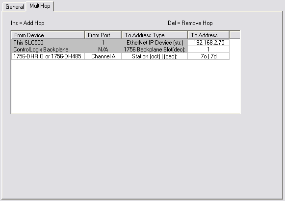
Sending Messages to DH+ devices
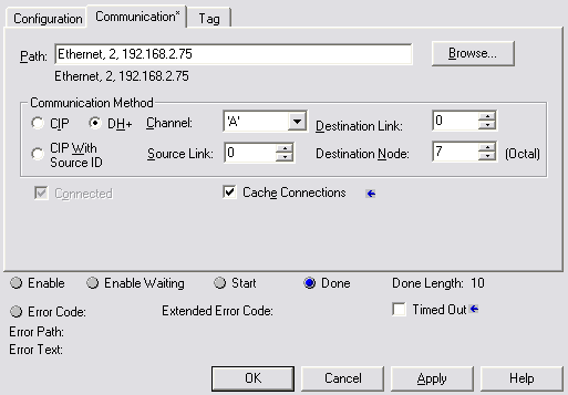
To communicate to nodes on the DH+ network using Ethernet/IP, the procedure is identical to using a ControlLogix Ethernet/IP to DH+ Bridge. When using a device like a SLC 5/05 to access the DH+ network, the message must be setup to use MultiHop addressing. Below is an example of how to setup the MultiHop portion of the message being sent to the EQ7000 to address node 7 on the DH+ network.
As can be seen, the message is setup like it is communicating to a ControlLogix Bridge. When communicating to the EQ7000 use a Backplane slot number of 1. Communicating to the EQ7000 using a ControlLogix has a different setup. The setup of the message is very straight forward. All that is needed is to enter the path that directs the message out the Ethernet/IP module to the EQ7000 and use the DH+ Communication Method to specify the node. The image below shows how to setup the message instruction to communicate to node 7 on the DH+ network through the EQ7000 at 192.168.2.75.
If using a SCADA or DCS software application to poll for data, setup the message as though it is communicating through a ControlLogix Bridge.
Communicating via AB Ethernet
The EQ7000 can accept messages sent by the AB Ethernet protocol. Therefore devices capable of communicating using AB Ethernet can access devices on the DH+ network.
Browsing specific nodes on the DH+ network is possible using RSLinx. To do this, an Ethernet driver must be configured in RSLinx with the IP address of the EQ7000 mapped to each node that exists on the network.
Browsing specific nodes on the DH+ network is possible using RSLinx. To do this, an Ethernet driver must be configured in RSLinx with the IP address of the EQ7000 mapped to each node that exists on the network.
Sending Messages to DH+ devices
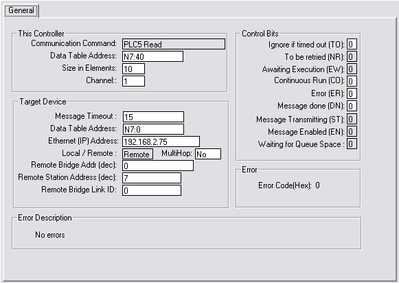
To communicate to nodes on the DH+ network using AB Ethernet, remote messaging must be used. Using local messaging will only allow communication to a single device located at node 0 on the DH+.
When using remote messaging, the source and destination link ID’s are not needed and can be left as 0. The destination address (or remote address) will be the value of the DH+ node address. Please note that DH+ uses octal notation and the application that is being used to setup the message may use decimal notation.
Below is an example of how to setup a remote message in a SLC 5/05 to read data from node 7 on the DH+ network through the EQ7000 at 192.168.2.75.
Browsing DH+ Network Using RSLinx
It is possible to browse known nodes on the DH+ network with the EQ7000 using the AB Ethernet driver in RSLinx. To do this, follow the steps below.
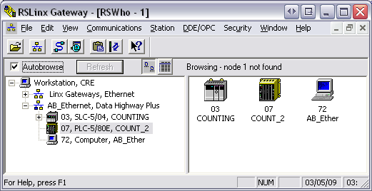
1. Open the Configure Drivers window and create a new Ethernet Devices driver.
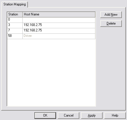
2. After creating the new driver, the configuration window for station mapping should appear. Enter the node address of the DH+ device in Station column and the IP address of the EQ7000 in the Host Name column. Repeat this step if there are multiple nodes to be browsed.
3. Once all the nodes are entered, enter the DH+ node address of the EQ7000 in the Station column where the Host Name is Driver. Below is an example showing DH+ nodes 3 and 7 being mapped to 192.168.2.75.
All Station numbers in station table mapping must be Decimal not Octal.
4. Once the driver is configured click OK to continue. Now that the driver is created, right click on the driver in the RSWho window and select Properties.
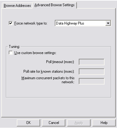
5. In the Properties window, click the Advanced Browse Settings tab. Check the Force network type to option and select Data Highway Plus. Below is an example of how the properties will be set. Click OK to close the window.
6. Now the driver is setup to browse the nodes specified in the driver configuration, highlight the driver that was just created and make sure Autobrowse is checked. The nodes should now appear as shown below.
In case your RSLINX version is any of the 3.6x you will not see the advanced tab, therefore you have two options.
A - Update RSLINX to latest version or any version after 3.70, that has the Advanced tab to force DH+ or DH485 network type.
B - Or have a separate driver for each PLC that you are trying to communicate with, but we recommend the 1st option which is to update RSLINX.
A - Update RSLINX to latest version or any version after 3.70, that has the Advanced tab to force DH+ or DH485 network type.
B - Or have a separate driver for each PLC that you are trying to communicate with, but we recommend the 1st option which is to update RSLINX.
Wiring
The diagrams below show how to connect the DH+ or DH485 network and Ethernet network to the EQ7000 in order to bridge DH+ or DH485 with Ethernet.
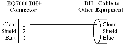
The diagram of the EQ7000 below shows the pin numbering for the DH+ or DH485 connector.
The diagram of the EQ7000 below shows the pin numbering for the DH+ or DH485 connector.
DH+ Connection

The diagram below shows the wiring for connecting the DH+ network.
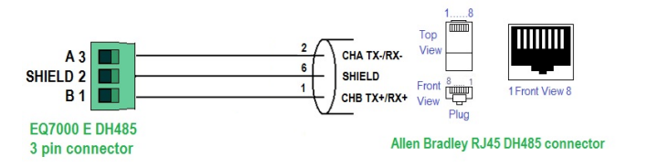
DH485 Connection
Two diagrams below show the wiring for connecting the DH485 network. Wiring for Allen Bradley DH485 6 pin Connector to EQ7000 EDH485
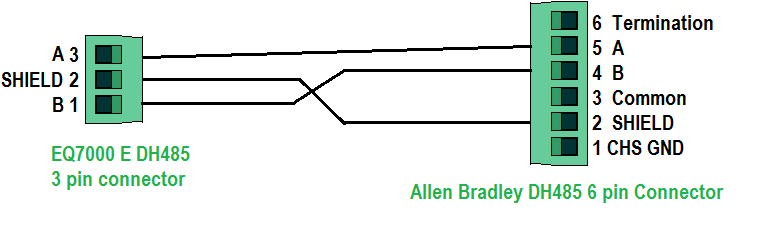
Wiring for Allen Bradley DH485 RJ45 Connector to EQ7000 E DH485
Ethernet Connection
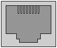
The diagrams below show the Ethernet wiring for straight through and cross over Ethernet cables. When looking at the RJ-45 jack, as shown to the left, pin 1 is the leftmost pin.
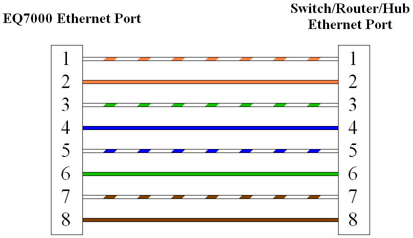
Straight Through Cable
The straight through cable is used when connecting the EQ7000 to a switch, router, or hub.
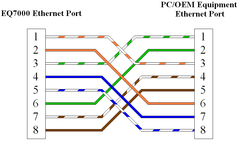
Cross Over Cable
The cross over cable is used when connecting the EQ7000 to a PC or other equipment without going through a switch, router, or hub.
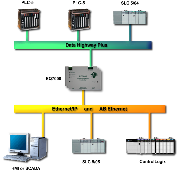
Typical Applications
Ethernet/IP and AB Ethernet to DH+
Below is a network diagram showing how the EQ7000 can be used to communicate between devices on Ethernet and DH+. Ethernet/IP and AB Ethernet capable devices can initiate requests for data from devices on the DH+ network by communicating through the EQ7000.