PDF Download
Configuring DL3500-DF1/DH+ or DH-485 With Wonderware’s InTouch MMI software Package
This application note is designed to aid the user in configuration of the driver software element
(ABKF2) of Wonderware’s InTouch MMI software package. This driver program is a separate element
of InTouch, and allows identification of the various addresses and protocols that the MMI program takes
to monitor/control various hardware components on the network, as designed in the main InTouch
window.
The Initial Driver Software Screen
Upon running the driver software program, the first screen that
appears allows three options under the "configure" menu:
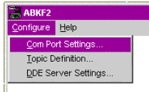
The three sub-menus involved in this configuration are covered in the following three sections:
1) Com Port Settings...
These settings configure communication between the computer and the DL3500. (Either via a serial
cable and an existing Com Port, or the USB cable and its corresponding Virtual Com Port)
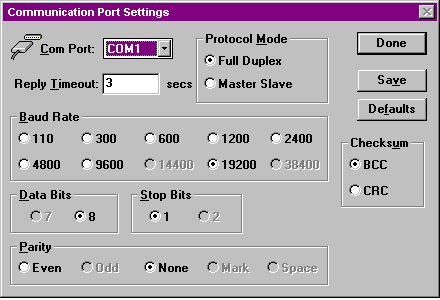 All settings must be consistent with those chosen when configuring the DL3500 with the DL32
configuration program. The latest version of DL32 is available at http://www.equustek.com/downloads.html
All settings must be consistent with those chosen when configuring the DL3500 with the DL32
configuration program. The latest version of DL32 is available at http://www.equustek.com/downloads.html
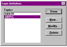
2) Topic Definition...
"Topics" are the communication properties and addresses that are used in the Wonderware application.
Each communication route between the various elements must be identified separately, and are given
distinct names.
Topic Name - Enter the name to be assigned. This name must be referred back to in the InTouch window.
Com Port - Enter the communication port over which the DL3500 communicates with the MMI. Connect Type - Enter the protocol with which the MMI communicates with the DL3500.
Node - (this setting appears within the "Network Addressing" section.)
a) The MMI's DL3500-DF1 unit may send and receive messages directly to and from the DL3500- Modbus Master (without going through the PLC to access the Modbus device(s). In this case, The address entered is that of the DL3500-Modbus. The tag entered in the InTouch program must provide the Modbus slave address (in dec) and the Modbus register location.
b) The MMI's may also access Modbus device information through the PLC. In this case, the address entered is that of the PLC, and the InTouch program's tag describes the location within the PLC data table where the Modbus device information is stored. When programming the PLC, it is crucial that the MSG instruction be programmed to access the local node address of the DL3500-Modbus device on the DH+ or DH-485 network, and the destination table address describe the Modbus address mapping.
Upon selecting "New..." or "Modify...” the following appears:
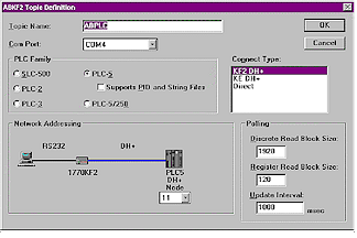
Topic Name - Enter the name to be assigned. This name must be referred back to in the InTouch window.
Com Port - Enter the communication port over which the DL3500 communicates with the MMI. Connect Type - Enter the protocol with which the MMI communicates with the DL3500.
Node - (this setting appears within the "Network Addressing" section.)
The appropriate choice depends on the mode of the DL3500 unit, and the network architecture.
See the following two cases on setting the NODE number.
Case 1 - Typical Installation:
In a typical installation, a PLC is being accessed; therefore
the address entered under “node” is that of the PLC. The
InTouch program's tag describes the location within the
PLC data table where the device information is stored.
The InTouch program's tag describes the location within the PLC data table where the device information is stored.
The InTouch program's tag describes the location within the PLC data table where the device information is stored.
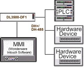
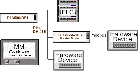
Case 2 - Accessing a Modbus Slave Device:
To monitor/control a Modbus
unit from the MMI, a converter
must be present in the network
to convert from DH+ to
Modbus. There are two ways
that the MMI may be set up to
perform monitoring and control
of the Modbus device(s):
a) The MMI's DL3500-DF1 unit may send and receive messages directly to and from the DL3500- Modbus Master (without going through the PLC to access the Modbus device(s). In this case, The address entered is that of the DL3500-Modbus. The tag entered in the InTouch program must provide the Modbus slave address (in dec) and the Modbus register location.
See DL3500-Modbus Master Application note for decoding
b) The MMI's may also access Modbus device information through the PLC. In this case, the address entered is that of the PLC, and the InTouch program's tag describes the location within the PLC data table where the Modbus device information is stored. When programming the PLC, it is crucial that the MSG instruction be programmed to access the local node address of the DL3500-Modbus device on the DH+ or DH-485 network, and the destination table address describe the Modbus address mapping.
See DL3500-Modbus Master Application note for decoding TAGS.