Delivering Moreģ
Application Note #1188: AGP to Allen Bradley DH+ via Gateway
PDF Download
Overview
This document describes how to connect a Pro-face AGP/AST display via a Pro-face
CA9-DH3000- PFA01 gateway to one or more Allen Bradley PLCs on a Data
Highway Plus (DH+) network. The Pro-face display communicates using the
standard GP-Pro EX Rockwell Automation DF1 serial driver through the gateway
residing on the DH+ network. Apply the Pro-face Multilink feature and multiple
displays can access multiple PLCs through a single gateway on the DH+ network.
This application note is an addendum to the Pro-face PLC/Device connection manual ōRockwell Automation DF1 Driverö. The sections in this guide supplement those in the manual. Refer to both documents to configure the gateway and DH+ application.
A major difference between the DL3500-Bridge and A-B network bridging products lies in its unique ability to bridge DH+ networks using local DH+ message commands. The protocol uses a flexible range addressing approach to allow DL3500Æs to be used in many custom bridging applications where A-B solutions are unsuitable or just too expensive.
It is possible you do not need a gateway. An AGP/AST display can be connected without a gateway to multiple PLCs via DH+ using the SLC5/04 pass-through feature. Include the Pro-face Multilink feature and multiple displays can access multiple PLCs on the DH+ network. For more information about this solution see Application Note 1180 ōAGP on Allen Bradley DH+ via SLC504 PassThruö.
1. System Configuration
The system configuration in the case when the External Device of Rockwell Automation PLC(s) and the
Display are connected is shown. Multiple PLC-5 and SLC504 PLCs on the same DH+ network can be
connected via a single gateway to the same AGP/AST.
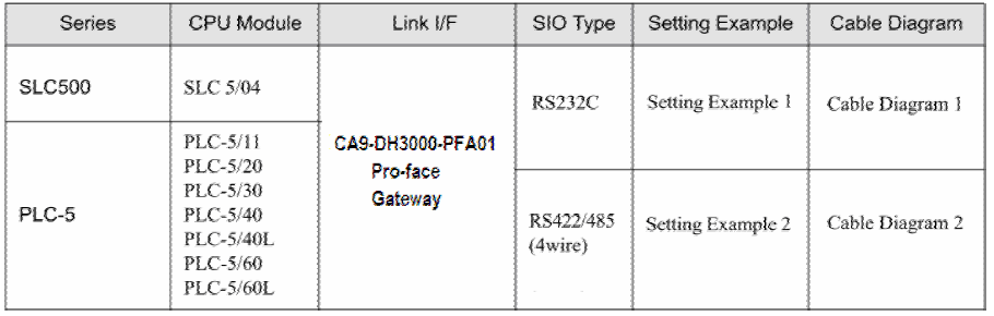
2. Selection of External Device
Refer to the Pro-face PLC/Device connection manual ōRockwell Automation DF1 Driver ōSection 2
Selection of External Device for a full explanation. To connect to the DH+ network use these settings
to select the Device/PLC:
Manufacturer: Rockwell Automation, Inc.
Series: DF1
Manufacturer: Rockwell Automation, Inc.
Series: DF1
3. Example of Communication Setting
3.a Setting Example 1
Settings of GP-Pro EX
Communications Settings
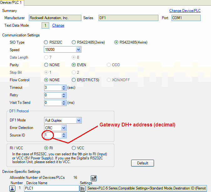
To display the setting screen, select [Device/PLC Settings] from [System setting window] in workspace. The communication settings of the PLC(s) are not considered. The communication settings should match the settings of the CA9-DH3000-PFA01 gateway. The Source ID should be the gateway DH+ decimal network address.
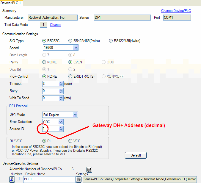
Device Setting
The device settings should match those configured in the individual PLC on the DH+ network. A separate device should be configured for each PLC on the DH+ network to be accessed by the GP-Pro EX project.
The device settings should match those configured in the individual PLC on the DH+ network. A separate device should be configured for each PLC on the DH+ network to be accessed by the GP-Pro EX project.
Series: SLC500 or PLC5
Destination ID (Remote): DH+ Node Address of the PLC (decimal)
Destination ID (Local): Not used
Compatible Settings Tab: Standard Mode (default)
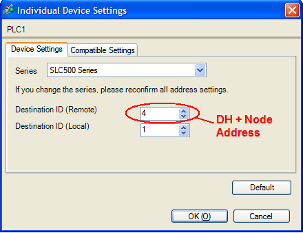
Note: For Full Duplex, "Destination ID (Local)" is not used.
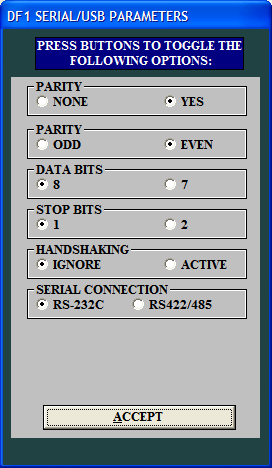
Settings of External DH+ Gateway Device
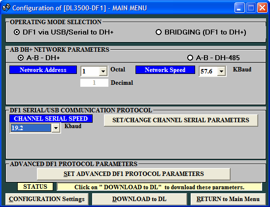
Install the Equustek DL32 configuration software provided with the gateway. Use it to configure the gateway communication settings. Connect your computer to the CA9-DH3000-PFA01 gateway using a USB cable or serial cable. On the ōWelcome to DL32ö screen click on DL3500 models. Click [yes]. Click on [DF1 to DH+/DH485]. Select the COM PORT the PC is using to communicate with the gateway . If you are using a USB cable check in Windows Control Panel under Device Manager for ōUSB serial port (com_)ö to find the assigned COM port number.
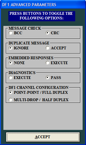
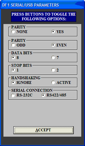
The settings should match those of the DH+ network and the connected Pro-face display. Select an available DH+ network address. The DF1 parameters should match the configuration of the connected Pro-face display. Other DF1 configuration settings:
Duplicate Message = Ignore.
Embedded Responses = None
DF1 Channel configuration = Point-Point / Full Duplex

Communications Settings
To display the setting screen, select [Device/PLC Settings] from [System setting window] in workspace. The communication settings of the PLC(s) are not considered. The communication settings should match the settings of the CA9-DH3000-PFA01 gateway. The Source ID should be the gateway DH+ decimal network address.
Device Setting
The device settings should match those configured in the individual PLC on the DH+ network. A separate device should be configured for each PLC on the DH+ network to be accessed by the GP-Pro EX project.
The device settings should match those configured in the individual PLC on the DH+ network. A separate device should be configured for each PLC on the DH+ network to be accessed by the GP-Pro EX project.
Series: SLC500 or PLC5
Destination ID (Remote): DH+ Node Address of the PLC (decimal)
Destination ID (Local): Not used
Compatible Settings Tab: Standard Mode (default)
Note: For Full Duplex, "Destination ID (Local)" is not used.
Settings of External DH+ Gateway Device
Install the Equustek DL32 configuration software provided with the gateway. Use it to configure the gateway communication settings. Connect your computer to the CA9-DH3000-PFA01 gateway using a USB cable or serial cable. On the ōWelcome to DL32ö screen click on DL3500 models. Click [yes]. Click on [DF1 to DH+/DH485]. Select the COM PORT the PC is using to communicate with the gateway . If you are using a USB cable check in Windows Control Panel under Device Manager for ōUSB serial port (com_)ö to find the assigned COM port number.
The settings should match those of the DH+ network and the connected Pro-face display. Select an available DH+ network address. The DF1 parameters should match the configuration of the connected Pro-face display. Other DF1 configuration settings:
Duplicate Message = Ignore.
Embedded Responses = None
DF1 Channel configuration = Point-Point / Full Duplex
3.b Setting Example 2
Settings of GP-Pro EX
Communications Settings
To display the setting screen, select [Device/PLC Settings] from [System setting window] in workspace. The communication settings of the PLC(s) are not considered. The communication settings should match the settings of the DL3500 gateway. The Source ID should be the gateway DH+ decimal network address.
Device Setting
The device settings should match those configured in the individual PLC on the DH+ network. A separate device should be configured for each PLC on the DH+ network to be accessed by the GP-Pro Ex project.
To display the setting screen, click the Settings icon of External Device you want to set from [Device- Specific Settings] of [Device/PLC Settings]. The Destination ID (Remote) is the Data highway Plus (DH+) Node Address of the PLC.
Series: SLC500 or PLC5
Destination ID (Remote): DH+ Node Address of the PLC (decimal)
Destination ID (Local): Not used
Compatible Settings Tab: Standard Mode (default)
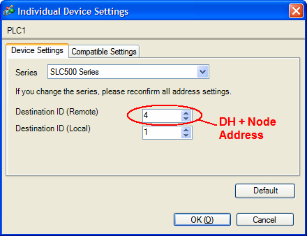
Note: For Full Duplex, "Destination ID (Local)" is not used.
Settings of External DH+ Gateway Device
Install the Equustek DL32 configuration software provided with the gateway. Use it to configure the gateway communication settings. Connect your computer to the CA9-DH3000-PFA01 gateway using a USB cable or serial cable. On the ōWelcome to DL32ö screen click on DL3500 models. Click [yes]. Click on [DF1 to DH+/DH485]. Select the COM PORT the PC is using to communicate with the gateway . If you are using a USB cable check in Windows Control Panel under Device Manager for ōUSB serial port (com_)ö to find the assigned COM port number.
The settings should match those of the DH+ network and the connected Pro-face display. Select an available DH+ network address. The DF1 parameters should match the configuration of the connected Pro-face display. Other DF1 configuration settings:
Duplicate Message = Ignore.
Embedded Responses = None
DF1 Channel configuration = Point-Point / Full Duplex

Communications Settings
To display the setting screen, select [Device/PLC Settings] from [System setting window] in workspace. The communication settings of the PLC(s) are not considered. The communication settings should match the settings of the DL3500 gateway. The Source ID should be the gateway DH+ decimal network address.
Device Setting
The device settings should match those configured in the individual PLC on the DH+ network. A separate device should be configured for each PLC on the DH+ network to be accessed by the GP-Pro Ex project.
To display the setting screen, click the Settings icon of External Device you want to set from [Device- Specific Settings] of [Device/PLC Settings]. The Destination ID (Remote) is the Data highway Plus (DH+) Node Address of the PLC.
Series: SLC500 or PLC5
Destination ID (Remote): DH+ Node Address of the PLC (decimal)
Destination ID (Local): Not used
Compatible Settings Tab: Standard Mode (default)
Note: For Full Duplex, "Destination ID (Local)" is not used.
Settings of External DH+ Gateway Device
Install the Equustek DL32 configuration software provided with the gateway. Use it to configure the gateway communication settings. Connect your computer to the CA9-DH3000-PFA01 gateway using a USB cable or serial cable. On the ōWelcome to DL32ö screen click on DL3500 models. Click [yes]. Click on [DF1 to DH+/DH485]. Select the COM PORT the PC is using to communicate with the gateway . If you are using a USB cable check in Windows Control Panel under Device Manager for ōUSB serial port (com_)ö to find the assigned COM port number.
The settings should match those of the DH+ network and the connected Pro-face display. Select an available DH+ network address. The DF1 parameters should match the configuration of the connected Pro-face display. Other DF1 configuration settings:
Duplicate Message = Ignore.
Embedded Responses = None
DF1 Channel configuration = Point-Point / Full Duplex
4. Setup Items
Refer to the Pro-face PLC/Device connection manual ōRockwell Automation DF1 Driver ōSection 4.
5. Cable Diagrams
Connection notes:
Refer to the Pro-face PLC/Device connection manual ōRockwell Automation DF1 Driver ōSection 4.
Ģ The FG pin of the External Device body must be D-class grounded. Please refer to the manual of the External Device for more details.
Ģ SG and FG are connected inside the display. When connecting SG to the External Device, design the system to not form short-circuit loop.
Ģ Connect the isolation unit, when communication is not stabilized under the influence of noise etc.
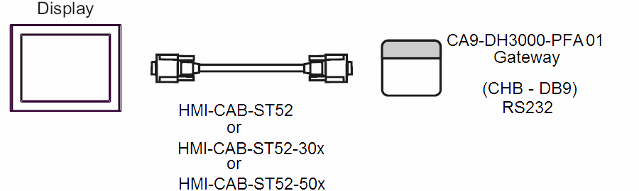
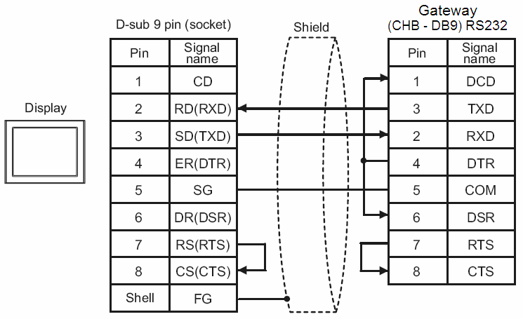
Cable Diagram 1
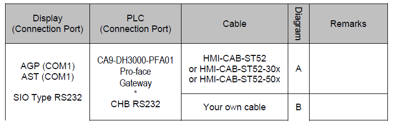 A) When using the RS232 cable (HMI-CAB-ST52) by Proface America
B) When using your own cable
Cable Diagram 1
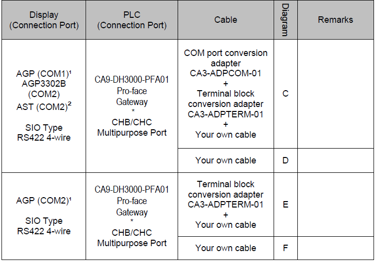
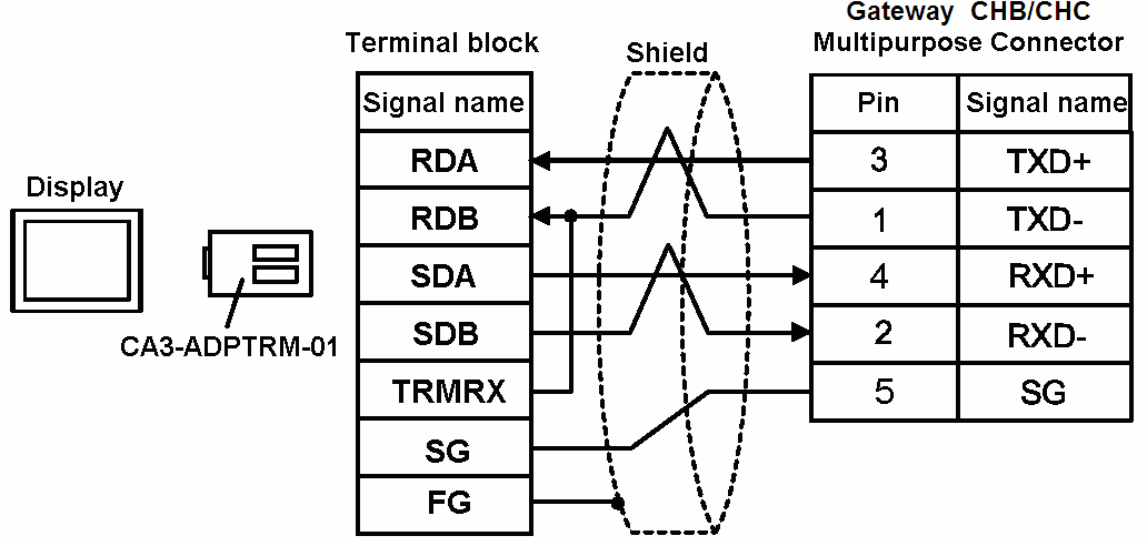
C) When using the terminal adapter and your own the RS422 cable to AGP (COM1)╣, AGP3302B (COM2), or AST (COM2) ▓.
*1 All AGP models except AGP-3302B
*2 All AST models except AST-3211B
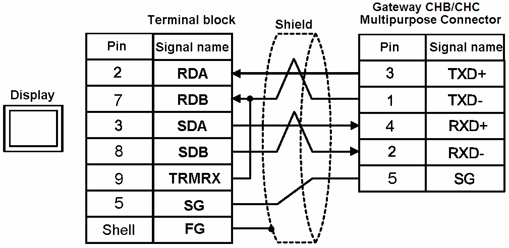
D) When using your own the RS422 cable to AGP (COM1)╣, AGP3302B (COM2), or AST (COM2)▓.
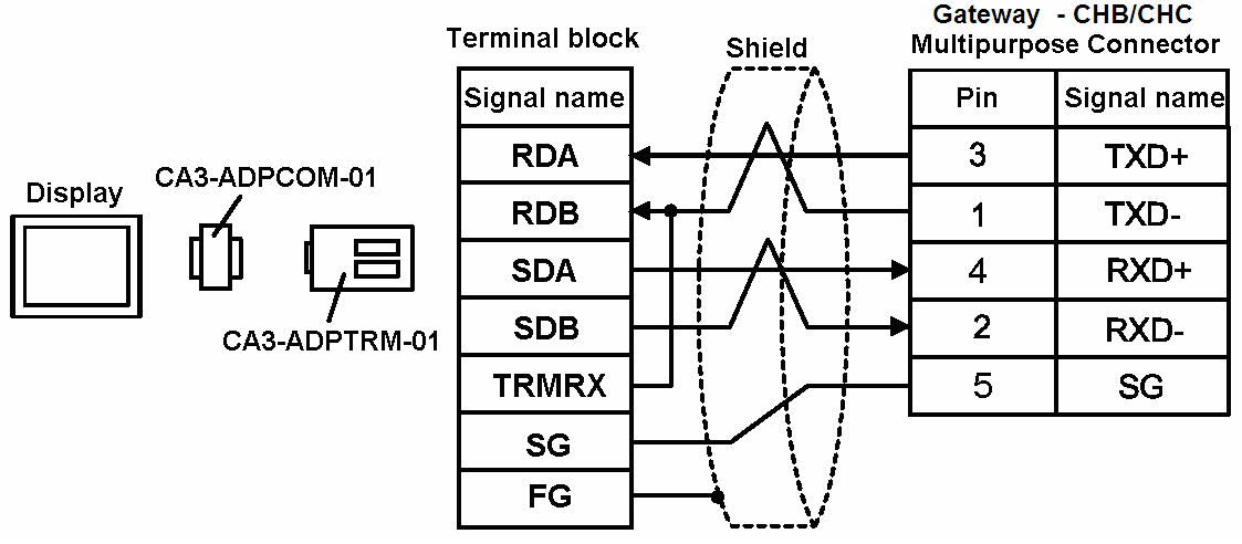
E) When using the terminal adapter and your own the RS422 cable to AGP (COM2)╣.
*1 All AGP models except AGP-3302B
*2 All AST models except AST-3211B
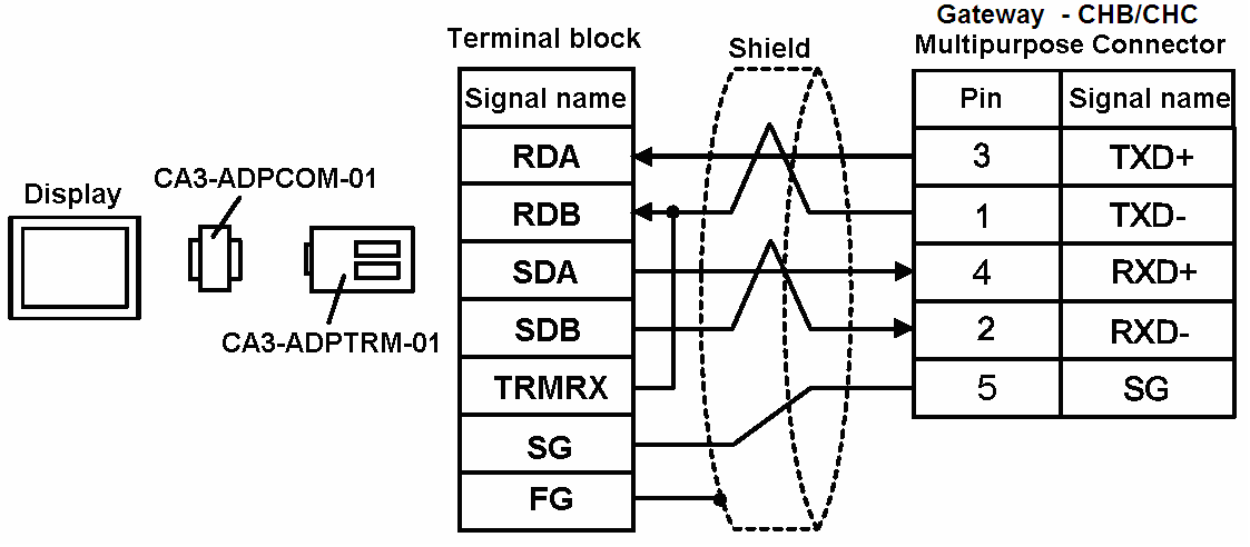
F) When using your own the RS422 cable to AGP (COM2)╣.
*1 All AGP models except AGP-3302B
Refer to the Pro-face PLC/Device connection manual ōRockwell Automation DF1 Driver ōSection 4.
Ģ The FG pin of the External Device body must be D-class grounded. Please refer to the manual of the External Device for more details.
Ģ SG and FG are connected inside the display. When connecting SG to the External Device, design the system to not form short-circuit loop.
Ģ Connect the isolation unit, when communication is not stabilized under the influence of noise etc.
Cable Diagram 1
B) When using your own cable
Cable Diagram 1
C) When using the terminal adapter and your own the RS422 cable to AGP (COM1)╣, AGP3302B (COM2), or AST (COM2) ▓.
*1 All AGP models except AGP-3302B
*2 All AST models except AST-3211B
D) When using your own the RS422 cable to AGP (COM1)╣, AGP3302B (COM2), or AST (COM2)▓.
E) When using the terminal adapter and your own the RS422 cable to AGP (COM2)╣.
*1 All AGP models except AGP-3302B
*2 All AST models except AST-3211B
F) When using your own the RS422 cable to AGP (COM2)╣.
*1 All AGP models except AGP-3302B
6. Supported Device
Refer to the Pro-face PLC/Device connection manual ōRockwell Automation DF1 Driver ōSection 6
7. Device Code and Address Code
Refer to the Pro-face PLC/Device connection manual ōRockwell Automation DF1 Driver ōSection 7
8. Error Messages
Refer to the Pro-face PLC/Device connection manual ōRockwell Automation DF1 Driver ōSection 8
For technical support email Pro-face America at support@profacamerica.com or call 734-944-0482.
For technical support email Pro-face America at support@profacamerica.com or call 734-944-0482.