Difference between RS485 and Profibus

When it comes to industrial networking, there are many specifications that govern the smooth exchange of information across hosts, slaves and throughout the network. All of these may be familiar with people who have mastered the art of network communication, but anyone who is starting out could be easily confused between the technical terms and accessories.

One such commonly confused pair of technical terms is the RS485 and Profibus.

Now people who do have a fair idea about the whole data exchange system in industrial networking would know that these are two very important contributors for smooth process automation. But, from a more detailed perspective, these are two different aspects related to the same concept.

Let’s get in to what each of these is.

Profibus

Profibus stands for Process Field Bus. It is basically a standard of fieldbus communication used in automation technology. And field bus refers to the network protocols used for real-time distributed control.

There are two versions of the standard being used in industries. One of them is Profibus DP which stands for Decentralised Peripherals and the other is Profibus PA which stands for Process Automation. Out of these the Profibus DP is more commonly used by industries while the Profibus PA is more application specific and is hence lesser used.

Profibus DP is meant to be used to control and operate sensors and actuators through a centralized platform for automation applications in production industries and factories. It includes diagnostic options as well.

Profibus PA on the other hand is mainly used to monitor measuring equipment through a process control system of course. It is specifically meant to be used in explosion prone or hazardous areas.

RS485

The RS485 is also a standard, but it defines the electrical signal levels in the communication between drivers and receivers or hosts and slaves in networking. In this case though, the electrical signalling is more balanced and multi point systems are also supported. For the same reason, the RS485 is a very useful and popular standard in industrial control systems. It is more so as it is capable of being connected with multiple receivers, whether in a linear or a multi drop bus and it supports both Local Area Networks as well as multi drop communication links and works with data rates up to 10 Mbits.

Difference between Profibus and RS485

Both the Profibus and the RS485 are standards used in communication during process automation. However, they are used in different aspects of communication.

Profibus is a very flexible and reliable communication technology where issues can be caused by small and simple errors. On the other hand, RS485 is a more balanced technology that makes use of a two-wire transmission system. In effect this makes it the difference in voltage between the two wires among which the communication or data exchange is happening. For the same reason that it doesn’t depend on the voltage directed to the ground, it is more stable. This also makes it less sensitive to interference when compared to a single-ended transmission.

Industrial Automation And PLC Programming; The Basics

In the field of industrial automation, we have been seeing and experiencing technologies that have made the process one step easier with each development. From the simplest computing devices initially developed to replace hardwired relays throughout industrial manufacturing processes, to complex systems that enable manufacturers to generate performance reports, industrial automation has come a long way and manufacturing units have been competing for the cutting edge with these advancements.

On the subject of advancements, two particular technologies that majorly revolutionized the concept of automation were PLCs and microcontrollers. Being on the same line of use, the two are quite often confused with each other and sometimes even understood as the same due to technical similarities.

Here is some insight into the major differences between them.

What is the difference between PLC and microcontroller?

To put things in to perspective, a PLC or a Programmable Logic Controller is basically a specifically designed computing device used in industry automation. They can be said to be one of the first and minor advancements in the field, as their initial purpose as mentioned before, was just to replace hardwired relays or timers or other sequences used in the industry. Now there are much more advanced versions of PLCs designed to be scalable and dynamic, compatible even with lines based on robotics. For the same reasons, they are the most commonly adopted computing system across industries. They are also known for their ability to work seamlessly in rough or rugged industrial environments, not to mention their real time responses that save time.

image1Microcontrollers on the other hand are much smaller computing devices when compared to PLCs. They essentially work on a single chip and they may contain one or more processing cores along with memory devices. The similarity with PLCs is that they too are used in almost all devices that play a role in daily activities, but the difference is that microcontrollers are specifically used in applications where only certain repetitive tasks are required to be performed. Additionally, they are also mostly bare and do not possess interface elements like display or switches like PLCs.

Suffice it to say PLCs are generally considered better equipped for advanced and complex industrial environments.

What are the three types of PLC?

There are 3 types of PLCs that are commonly used in industrial automation, based on their levels of complexity and functionality. They are:

Unitary – which is the most basic and simplest type of computing device. It usually uses a single box to contain all of its system components including the processor and its input and output ports.

Modular – which typically consists of several modules that can be clubbed together to form a customized computing device. It has a base module that takes care of regular or core functions including input connections, electrical power monitoring etc. The extra modules are usually signal converters or additional outputs that can be added as per requirements.

Rack Mounting – which is similar to the modular PLC, but differs in that each of the modules is usually distinguished from one another, unlike modular when each of them is connected to the base module. In Rack Mounting, all the additional modules are connected through a network and the modules are organized in the form of racks.

image2

What are the main components of PLC?

Typically, PLCs consist of 6 main components namely, the input and output modules, the power supply, the peripheral or interface components, the coprocessor modules and most importantly, the Central Processing Unit (CPU) which stores and runs the software programs processed by the software unit.

What is Allen Bradley software?

Allen Bradley has been one of the most trusted and reliable names in the field of process automation software since its pioneer in the computing technology. Allen Bradley software basically consists of a group of intelligent and support technologies or products including input and output modules, programmable controllers or PLCs, motor control centres, portable data collectors, sensors and the like that aid industrial automation.

What is Allen Bradley PLC programming?

Allen Bradley PLC programming thus describes the use of Allen Bradley software, more specifically the brand’s PLC in industrial automation. It is symbolized by robustness, reliability and of course high performance. High levels of efficiency are often associated with industries that use Allen Bradley PLC programming, as the brand’s systems are carefully designed to work seamlessly in complex industries.

Image sources:

https://www.myodesie.com/wiki/index/returnEntry/id/2962

https://www.elprocus.com/programmable-logic-controllers-and-types-of-plcs/


What is the purpose of DP DP coupler?

The DP DP coupler is used for connecting two Profibus networks with each other for enabling data transmission amongst the controllers of both the Profibus networks. For input and output transmitted data, the utmost length is of 244 bytes.

The outlining of the DP DP coupler is done using a software design tool that assimilates the coupler using a GSD file.

maxresdefault


What are the properties of DP DP coupler?

  • Dual power supply
  • Electrical isolation between the DP networks
  • Different transmission rates and Profibus addresses on both sides of the coupler
  • DP1 is supported with uniform and full diagnostic functioning
  • It is robust. That means even if one side fails, it will retain the output values of the other side
  • Offers up to 16 input/output areas for data transmission
  • Of the 244 bytes of input and output data exchanged, 128 bytes are consistent
  • Easy to set up the Profibus addresses using software or DIP switches
  • Profibus-DP up to 12 Mbps
  • Automatic baud rate recognition

For safety reasons, the DP DP coupler can be coupled with two different power sources concurrently.

The DP DP coupler allows the Profibus to rapidly transfer the processed data between the decentralized field modules like drives or slaves and central controller modules like PC or PLC.

During normal operation, the central controller cyclically reads the input of the connected decentralized field modules for sending the output data to them. The maximum of 244 bytes of output and input data can be transferred in one cycle.

Apart from the user data traffic, the DP DP coupler offers wide-ranging diagnosis and authorizing functions. The current diagnosis messages of the decentralized modules are summarized in the central controller modules. This enables a rapid localization of errors.  

Features of Profibus-DP

  • Bus length up to 100 meters at 12 Mbit/s and up to 1200 meters at 9.6 kbit/s
  • An optical fiber or twisted pair cable as a medium for bus
  • Up to 126 subscribers with repeaters (one bus) and 32 subscribers without repeaters
  • Integrated repeater controller
  • Synchronization of outputs and inputs through control commands

G_IK10_EN_40007P

The DP DP coupler ensures the independence of both the Profibus networks. That means you need to configure an individual Profibus address for every Profibus-DP network.   

It is crucial to comply with the accident prevention and safety regulations like machine protection guidelines when using the Profibus-DP. Certain equipment must retain an operational state in all operating modes.


Image Sources:

https://www.google.com/search?safe=active&tbm=isch&q=dp+dp+coupler&chips=q:dp+dp+coupler,online_chips:profibus&usg=AI4_-kSiheXq3EPmg2fs4xsv99RhvUXbRQ&sa=X&ved=0ahUKEwiU6fbtx-XfAhWKto8KHVTgCPwQ4lYIKygD&biw=1440&bih=772&dpr=1#imgrc=sX_tutifC5WOzM:

https://w3.siemens.com/mcms/industrial-communication/en/ie/network-transition/ie-pb-link-pn-io/pages/ie-pb-link-pn-io.aspx

Modbus vs Profibus- Advantages of Modbus Over Profibus

In today’s world, there are many different protocols, and some are better equipped to work in different applications. Modbus and profibus each have strengths, and there is some overlap as to what each of them is capable of. Some people, however, consistently prefer to use modbus over profibus.

binary-codeModbus was originally designed in the mid 70’s and was a proprietary protocol for Modicon. The company published it royalty free before finally making it an open protocol. Many companies began using it, and because of this, there are now several variations. Even though it has variants, it is best described as simple. It’s easy to implement and easy to use. This is one of its biggest strengths. The specification document is less than 100 pages, which indicates its simplicity. Modbus usually refers to one of three protocols – Modbus ASCII, Modbus RTU, or Modbus TCP/IP.

Modbus ASCII was the first modbus, and usually runs on the RS-232 or the RS-485 physical layer. There is one master and all slaves are polled on demand by the master. The message frame can be up to 253 bytes.
Modbus RTU is a variation of Modbus ASCII. The difference is the encoding of the data. RTU uses bytes to encode messages, which increases the throughput.
Modbus TCP/IP was added much later, and can be thought of as, essentially, a way of encapsulating an RTU packet within a TCP/IP packet. It’s simple to use, but is slower than other Ethernet products. It is still adequate for monitoring applications.

As Modbus is a simple master slave protocol, and the master has full control of the communication. The slave will only respond when asked. The master will record the outputs, and read the inputs from every slave during every cycle. The slave devices don’t join the network, and they only respond when spoken to, and remain idle when they are not being spoken to. There’s no requirement for a watchdog timer, and there’s no requirement for diagnostics for the slave’s health.

Modbus usually uses the RS232 or the RS485 physical layer, but it can also use other physical layers, like phone lines, or wireless. RS232 and RS485 were established physical layers during the Modbus original development, and it didn’t add any new requirements.

In the case of using phone lines and wireless, Modbus has excelled. Phone lines and wireless introduce delays in the messages, which can be problems, but Modbus either deals with this, or it adapts to work in these applications.

Modbus can be used from a controller, or monitor to a smart device, controller, or monitor to a smart device from multiple vendors and for remote monitoring of information from a smart device.

Profibus is not only more complicated to implement and use, but it also uses specialized characteristics which tie it to RS485. RS485 is used in many different industries but it will become obsolete. Modbus, on the other hand, is always going to grow and be utilized because of its simplicity, and because it can be adjusted to the Ethernet, without overly complicated processes.

However, it is possible to utilize both protocols to work together. Modbus is the data transport between a master controller/data concentrator and has a remote profibus station. Using both protocols allows the simple implementation and easy modem support of modbus, while also gaining some positives from profibus. Profibus can be used in hazardous and multi vendor applications, and modbus provides a link between a SCADA system and a data concentrator.

What is a programmable logic controller?

pROGRAMMABLElOGICcONTROLLER
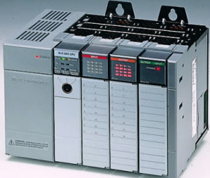
This is a digital computer which is specially adapted for the control of manufacturing processes such as assembly lines, lighting fixtures, robotic devices, amusement rides or activities that require high-reliability control, process fault diagnosis and ease of programming.

Programmable Logic Controllers (PLCs) have progressively become a fundamental part of the industrial environment. It is imperative to understand their basic functionalities as a technician involved with PLCs controlled processes.

PLCs are designed for multiple arrangements of input and output, resistance to impact and vibration, electrical noise immunity and extended temperature ranges.  The programs are written on a computer and then downloaded to the PLC. The Programs to control machine operation are stored either in non-volatile memory or battery backed up RAM.  A PLC allows for output results in response to input conditions within a set time.

A brief history of the PLC

Before the PLC, sequencing and control for manufacturing were composed of drum sequences, relays, and closed-loop controllers. The process of updating these was expensive and time-consuming because it required individual rewiring of relays.

PLCs were invented to replace the rewiring of relay based control panels in the American automotive industry when there was a change in production models.

GM Hydramatic, which is General Motors automatic transmission division, issued a request in 1968 for the hard-wires relays systems to be replaced. Bedford Associates of Bedford, Massachusetts gave the winning proposal.

Bedford Associates started a new company dedicated to developing, manufacturing, selling, and servicing this new product which they named MODICON (MOdular DIgital CONtroller). One of the very first 084 models built was decommissioned after almost twenty years of nonstop service. The automotive industry remains one of the largest users of PLCs to date.

Previously, the sequencing and control for automobiles manufacturing relied on hundreds of relays, dedicated closed-loop controllers, drum sequencers, and cam timers. Updating such facilities was costly and time-consuming, as technicians needed to manually and individually rewire the relays.

When digital computers were invented, they were used in in industrial processes to control combinatorial and sequential logic due to their general-purpose programmable devices. However, these early computers required programming specialists as well as rigorous operating environmental control for cleanliness, temperature and power quality. To overcome these challenges, the PLC was developed with several key attributes. It would tolerate a harsh environment; effortlessly support discrete input and output. Also, its operations could be monitored and would not require years of training to use.

Advantages of PLCs

Reduced Cost: PLC prices range from a few hundred to a few thousand. PLCs are cost efficient because they eliminate shipping and installation costs.

Flexibility: A single PLC can effortlessly run many machines.

Ease of Troubleshooting: With PLC control, any changes in sequence or circuit design are as simple as retyping the logic. PLCs allow for a fast and cost effective way of correcting errors. Moreover, a PLC program can be tested after it is developed before it is implemented in the field.

Space Efficient: A PLC requires fewer components than conventional hardware systems making them space efficient.

Visual observation: PLCs have a visual display on a screen which makes troubleshooting simple and fast.

Components of a PLC

All PLCs have the similar basic components. These include controller relay units for input and output, timers, CPU, a peripheral device, communication processor (CP), interface module (IM) and power supply. These components work jointly to carry information into the PLC, evaluate that information after which the information is sent back out to various fields.

Modbus RTU vs Modbus TCP/IP

Modbus RTU and Modbus TCP/IP are usually communication protocols. The communication protocol is the system of rules, which permit two or more entities to package and transmit data, and are implemented in software and hardware. Networking of industrial devices like level sensors to a PLC and pressure transducers is achieved by using a kind of communication protocol referred to as Fieldbus. Modbus is a widely used Fieldbus, which supports two-way communication for a remote operation like set-up and programming and permits transferring lots.

TCP/IP and RTU are two popular types of Modbus. Basically, these are two different methods of data transmission. While the way structured data for transmission is defined by Modbus, wrapping the data structured for specific ways of transmission is defined by TCP/IP and RTU.

Modbus RTU

A network of field devices that use serial communication is known as Modbus RTU. You can interconnect Modbus devices and sensors in a network.

  • RTU is widely used for industrial control networks because it has been in existence for long around, and it is supported by lots of software and hardware.

Modbus TCP/IP

The creation of Modbus TCP/IP came about so as to maximize the benefits of an Ethernet network. Essentially, Modbus RTU that uses the TCP interface in an Ethernet network is what is called Modbus TCP/IP. The structure of Modbus data is defined with the use of the application layer applied in the TCP/IP protocol. The TCP is utilized to make sure data is received and sent the right way, and the address and routing information is described as IP.

Basically, the Modbus TCP/IP command is a Modbus RTU command, which is included in an Ethernet TCP/IP wrapper.

  • The advantage of using Modbus TCP/IP is with the use of the existing Ethernet network equipment, which is inexpensive and widely available.

Generally, TCP/IP and RTU exist to help you transmit data in a manner which is comfortable and inexpensive for you. Contact us today us to talk about your particular application, and assist you in determining the best way to transmit data.

Controlnet vs Devicenet

The Difference Between ControlNet and DeviceNet

When it comes to connecting floor-factory devices in a cost effective way, DeviceNet is a communication network that is open and effective. These floor factory devices include push buttons, sensors motor starters and drives as well as control systems that deliver data at fairly good speeds of approximately 125 to 500kbits/s making it the leading market device for networking. DeviceNet is also efficient for simple devices, since the length of its messages that often exchange range from about 0 to 8 bites. Additionally, in the case of sending longer messages, there is message fragmentation that makes it possible for the data to be availed in numerous packages.


DeviceNet has a clear market spot with device level communication since there is no other kind of network that has the capability to transfer controlled data and information in small packages that are also pocket-friendly. There is a considerable cost barrier when it comes to implementing IP/ Ethernet at the device level since DeviceNet, uses a cable configuration with a multi-drop. The multi-drop can allow you to connect up to 50 devices on a single cable. A switch (point-to-point) configuration is needed for Ethernet to be functional for control applications. There are up to 50 wires that run between the devices and the switch. TheDeviceNet design is common in several companies with high volume automotive production. The design is known as CAN and it is simple without the need for memory in its controller or device. This ensures a cheap outcome component that is as low as $1 and is available from various chip manufacturers. Additionally, the CPU may only need to have the CAN protocol without any additional components of communication, hence, making it rather easy and cheap to use commercially for profitable products and systems.

The Newest Mode of Transportation- Ethernet/ IP

ControlNet International published and accepted the layer application that was shared by both DeviceNet and ControlNet over Ethernet in the spring of 1998 when ControlNet applied CIP. The standard Ethernet/ IP was introduced by ControlNet International as well as other open network organizations. Ethernet users enjoyed information and control services from the open application layer.

What are the differences between the new EtherNet/ IP and the Ethernet that has been around for over 20 years?

To begin with, the major difference is that a common language must be met so as to choose products from various vendors so that they could operate hand-in-hand on the plant floor. For the last ten years, there have been several vendors who have been applying their layer of Ethernet products that have been presented to the market. Consequently, the data sent by vendor A’s product is not comprehensible by vendor B’s Ethernet product. However, when trying to take advantage of the current rich, analytical products this is not the ultimate circumstance one would like to be in.

Additionally, Ethernet/ IP gives its users the ability to control the network, acquire data diagnose capabilities as well as configure the device. It uses the TCP/IP protocol that is standard, therefore, controlling the messages and permitting information.

The commercial component availability, current architecture, and the experience of the users has led to the evolution of Ethernet/ IP. It is essential to consider the cost of the devices in that the commercial Ethernet PC card costs only $20 while the industrial controller may be more than $1,000. The Central Processing Unit and the memory are necessary in the module in order to perform the tasks of the PC, hence the difference of the costs. Also, the industrial products are made to resist increased levels of humidity, temperatures, shock, vibration, as well as electric interference as compared to the products sold off-the-shelf.

The reduced pricing of Ethernet might be connected to the training and manpower needed making it a preferable device for several IT and IS departments for many years. The extensive exposure to the Ethernet technology has led to expansive knowledge as well as unmatched resources. Besides being fast, it has a significantly high data transfer rate as compared to other networks.

Real-Time Control Using ControlNet

Why is ControlNet a common selection yet users can still have real-time control with Ethernet? It is because ControlNet offers a faster link and can handle complicated control systems such as weld control, coordinated drive systems, vision systems, complex batch control systems, motion control as well as the process control systems. This is because it has huge data requirements, and multiple controller systems and human machine interfaces. It also has the best system with multiple controllers joining all the different controllers such as PCs, robots, and welders.

ControlNet users are loyal to it because it can handle control systems that are complicated by the presence of passive taps making the network unpowered. The passive taps ensure that a loss of any of the nodes will not lead to network failure. On the losing side, Ethernet has powered switches meaning that loss of power will result in loss of network. For this reason, users will opt for ControlNet to ensure extensive media redundancy, cabling options that are safe and other features related to ControlNet.

The applicants of ControlNet would want the following advantages:

  • Multi-Media Options
  • Complete solution for product availability
  • Engineering Productivity with Deterministic Performance
  • System uptime with Media Severance
  • Designed Safe cabling for Process Control

Engineering Productivity with Deterministic Performance

The configuration software of ControlNet assists in eradicating any clashes within the configuration and errors in the device by monitoring the usage of the network bandwidth as well as the communication rates of the device by notifying users in case hitches come up. The additional software is helpful in that; Users can configure a sensor that is updated every 5ms as well as drives to update every 10ms and make confirmation that there is enough bandwidth. The sensor and the drive are updated as programmed without network interruption from activities that use the network such as messaging and configuration.

Complete Solution from Product Availability

The advancements of ControlNet and the customer requirements ensure that the clients can choose from a wide variety of products. At www.controlnet.org, there is an exclusive list of products from ControlNet International and it keeps growing in number and variety of its choices.

System Uptime with Media Severance

Physical media redundancy is standardly offered by ControlNet. There is the assurance of extra security against a cable being damaged or cut. On execution, each device has a connection to two cables and the same data is transmitted parallel on each cable. In the case that either of the cables is not functioning but the operation continues uninterrupted without the loss of communication, the alarms are sent to the management system without manual intervention.

Designed Safe Cabling for Process Control

ControlNet offers naturally safe cabling options because of its design with passive network components that can be used in dangerous situations such as I/O and other components. Additionally, fiber optic cabling makes use of barriers that segregate dangerous areas.  Using ControlNet as well as the design of the system offers a cost-effective system that is relatively simple.

Multiple Media Options

ControlNet offers flexibility with its cabling components that are used when designing an application. The trunk cable is available in optical and coaxial fiber and makes up the central backbone of the system. The users use their environments to pick out the most suitable media. Also, there are special cables used that are flexible with special insulation material and much more. In order to connect devices and gaps to the networks, a BNC connector is used. The fiber and coaxial repeaters extend the length and create a ring, star or tree configuration.

Have you chosen the Right Bus?

When looking for an effective way of transferring data from a device to the internet, it is important to select the best means of transportation. Many travelers and plant managers enjoy the freedom of choosing between a variety of travel options such as planes, buses, and trains among others. All the same, you are the one who knows the best network for your application and whether it would be DeviceNet, ControlNet, Ethernet/ IP or a blend of all these networks.


What Is Modbus TCP/IP ?

The Modbus TCP/IP, or Modbus-TCP is similar to the Modbus RTU protocol, but with a TCP interface that runs on Ethernet. The Modbus messaging structure is an application protocol that rules the organization and interpretation of data independently of the data transmission medium.

TCP refers to the Transmission Control Protocol, while IP refers to Internet Protocol. These two protocols are the transmission medium for the Modbus TCP/IP messaging. Essentially, the Modbus TCP/IP exchanges blocks of binary data between computers. This protocol is also considered to be a world wide standard and provides a foundation for the World Wide Web. The TCP is to ensure all the packets of data are received correctly, with the IP ensuring that the messages are addressed and routed correctly. This TCP/IP combination is the transport protocol, it is the Modbus application protocol that defines what the data means, and how it is interpreted.

To summarize, the Modbus TCP/IP uses Ethernet and TCP/IP to transport Modbus message structure data between compatible devices. What this means, in essence, is that it combines the physical network of the Ethernet, with the TCP/IP networking standard and the Modbus application protocol as a standard of data representation. So, it is a Modbus communication with an Ethernet TCP/IP wrapper.

The Modbus and user data are contained in a TCP/IP telegram, but are not modified at all. The Modbus error checking field, checksum, isn’t used. The standard Ethernet TCP/IP layer checksum methods are utilized instead to guarantee the integrity of the data. The Modbus frame address field is replaced by the unit identifier in Modbus TCP/IP, and is part of the Modbus application protocol header.

If you are in need of Modbus Gateways please see our product line here

DH+ APPLICATION CONSIDERATIONS

Application Guidelines

When configuring a DH+ link for your system it’s important to consider the following application guidelines.

  • To achieve acceptable response times, you will need to minimize the number of DH+ nodes. It’s important when minimizing DH+ nodes to keep frequency and size of the messages exchanged between devices in mind.
  • To achieve the fastest control response time possible, you’ll need to limit the number of stations on your overall network. To bring on additional stations, establish separate DH+ networks.
  • Never remove or add stations to the network during process or machine operation. If the network token is situated with the removed device, it can be lost to the rest of the network. Automatic re-establishment of the network could take several seconds to activate. During this time, control is interrupted or unreliable.
  • Try to avoid programming controllers as much as possible online during process or machine operation. This could increase response time by possible long bursts in DH+ activity.
  • Add a separate DH+ link where possible for processor programming to keep the effect of programmed terminals from the process DH+ link.


What Is Industrial Automation Engineering Technology?

With the increase in demand for industries to manufacture and produce top quality products, it’s important that the technology and industrial automation services behind the company is sound to ensure smooth operation of the business each and every time. Automation engineering technology is used by many industries to produce an abundance of items ready for market and resale, amongst other things. But what exactly is automation engineering technology you ask? The following is a brief guide to what this technology is so you can be more informed.

industrial automation servicesWhat Is Industrial Automation Engineering Technology?

Automation engineering technology is the term that’s used for a variety of systems which include process controls and communications. Technicians in the industrial automation engineering field generally combine key fundamental principles of mechanical engineering technology with electronic and electrical circuits to develop, design, test, and manufacture computer controlled and electrical mechanical systems which are becoming a key foundation element in industrial industries.

The industry of automation is a branch of the electronics field and is fast becoming one of the major growing areas of international and national high technology economies. Industrial automation engineering technology features a combination of electronics, mechanics, and electrical, and includes the control or interaction of computers, motors, hydraulics, pneumatics, and other processes which are applied and used within manufacturing.

What Do Automation Engineering Technicians Do?

Industrial Automation engineering technicians use theories and principles of engineering, science, and mathematics to come up with solutions to technical problems in areas of development, research, inspection, construction, manufacturing, and maintenance. More practically orientated than most engineers and scientists, automation engineering technicians general assist in the research and development process of ordinary scientists and engineers.

The areas where automation engineering technology is used includes in quality control environments. This means the inspection of processes and products, along with the process of collecting data and conducting test.  In the area of manufacturing, technology is used to help with the product development and design, along with the production process. Programmable logic controllers or PLCs are a significant area where automation engineering technology is used. This involves conducting work with special-purpose computers to create synchronization of the different technologies which are used within the manufacturing process. Automation engineers who are familiar with PLCs generally setup and use the special-purpose computers.

Conclusion

Automation engineering technology plays a major role in many businesses and industries. If you’re a business that requires an automation engineering technician it’s best to check their credentials and ask them questions about what they can help you with to make sure you find the right technician to suit your individual needs.


1 2 3 4 5